Lifelong Learning Knowledge should be uncompromisingly sought after and freely given away.

8Mar/190

A simple dual MQTT button…

I seem to be on a roll lately with these ESP8266 based projects, but they are so fun and useful, it's not difficult to identify new uses. This project originated from another project I just completed, building my own solder fume extractor. I wanted an easy way to turn the fume extractor on and off as well as having a timer turn it off after a few hours (in case I forget to turn it off). I immediately thought of a USB-powered MQTT "button" that would toggle the fume extractor on and off. But hey, if I was going to have this feature for my fume extractor and bother with incorporating it into my HASS.IO server, why not add another button and allow it to toggle two switches. I could use the other for my soldering iron, which sadly does not have an automatic shutoff built-in. And if they are both accessible to my HASS.IO server, why not automate and coordinate them? But first...

As with all of my projects, I listed the problem(s) I was trying to solve and my requirements for a solution.

Problems I wanted to solve:

  1. Eliminate the need to plug in and unplug the fan power cord on the fume extractor every time I want to use it
  2. I often forget to turn on the fume extractor when soldering
  3. Shut off the extractor after a few hours (in case I forget) or when the soldering iron is turned off
  4. I have been known to forget to turn off my soldering iron

So, four primary problems to solve. What are my requirements?

  1. Switch or button within easy reach while sitting at my lab desk
  2. Leverage HASS.IO to control the Sonoff plug on the extractor and the Sonoff plug on the soldering iron
  3. Not take up any desk space
  4. Use up some of the numerous ESP-12S modules I already had on hand
  5. Have nice large buttons (I love arcade buttons)

Since I knew I wanted to leverage 28MM arcade buttons and I needed two, I started this project with the design of the enclosure. It's silly large because of the arcade buttons, but I planned to mount the whole enclosure under my desk anyhow, so size was less important than my desire to use ARCADE BUTTONS! I only challenge in the build for this enclosure was that I had decided I'd try my hand at mechanical retainers to hold the PCB in place, I ended up exporting the PCB design from EagleCAD into Fusion 360 and building the enclosure around it. The design allows the PCB to be slid into the slot from the back and a small tab holds the PCB in place once it's fully slid into position.

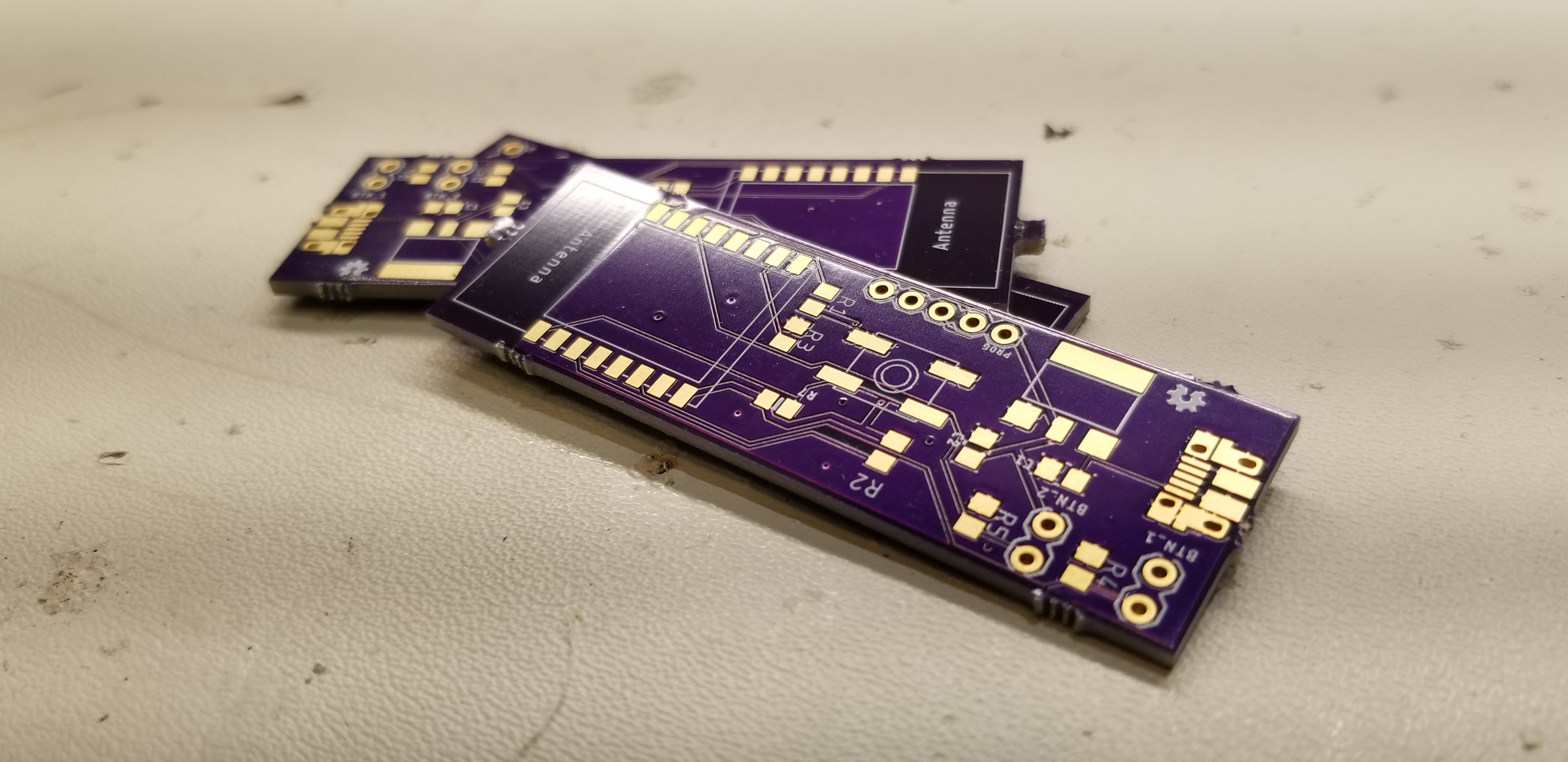
The next task was to design the actual PCB, which was super simple this time. I have already used all of these components andwas able to put this one together in about an hour. Although, in full transparency, I did send the first version off to OSHPark to fabricate only to realize I had put the USB connector on the board backward; speed and quality are always in conflict it seems. With that silly mistake resolved, I was good to go with this step.

The last step was writing the firmware for the ESP8266 and modifying my HASS.IO server settings to add the new button (switches) and automation to trigger the appropriate Sonoff switches when the buttons are pressed. The Arduino code is very straightforward. The modifications to my HASS.IO configuration was a bit tricker, I didn't really want to deal with having the MQTT button query the state of the switch and issues an "ON" or "OFF" command, I just wanted it to "TOGGLE" the switch, regardless of its current state. I ended up figuring out that I could trigger a toggle command on the Sonoff switch based on any published message to the MQTT button topic. What this means is that my automation will trigger anytime any message is published on the MQTT button topic, doah. Sometimes things are just easier than you'd expect. I just had to add a second automation for the second button and test things out.

Testing was great, the only bug I found was that I had swapped the button IO pins on the PCB in firmware. A quick reflash of the ESP8266 with the fixed firmware and it was all good. As soon as the button is pushed for the fume extractor, it comes on, super low latency. Same was true for the second button that controls my soldering station. It was working and working perfectly!

One last enhancement needed to be developed, however. I wanted to automatically turn on the fume extractor when the soldering iron was turned on as well as turn it off when the soldering iron was turned off. However, I wanted to allow independent control of each so I could easily override the automation of the two, thus the two buttons. Doing automation in Home Assistant (HASS.IO) is fairly straightforward, lots of great community articles on how to write them, so no need to poorly attempt to instruct anyone on that here.

Overall, I'm absolutely thrilled with this project, it was incredibly easy to execute on and the reward; it makes me smile each time I get to smash that arcade button and hear the soft whirl of the fume extractor!

As with all my projects, all the artifacts for this project can be found on my GitHub repo for the project here.

4Mar/190

A smarter doorbell (without all the extras)

Automating my home has been a journey I've been on for several years now and at no point in that journey did I feel the necessity for a $200USD  doorbell. Not that I don't see use cases for it or think others couldn't have a compelling use case for them, I, however, could never identify a use case that justified the purchase costs (and potential monthly subscription costs). Not to mention I absolutely hate products that require cloud services to function. There are far too many instances of companies deciding to shutter their cloud offering or otherwise discontinuing the service which most times, leaves the product only useful as a doorstop.

Recently, however, I did find a use case for some improvement in our current doorbell situation. Our doorbell is wired, but it's tough to hear from anywhere but the living room. I tried replacing the doorbell with a newer model that was supposed to be louder and yet it still didn't help. I wanted to be able to hear the doorbell from any room in the house (basement included). I also wanted an SMS or other notification when someone rang the doorbell. What I didn't want was any cloud-connected solution, video or bi-directional audio. I didn't see the use case for those features. I also wanted to keep the aesthetic of our wire doorbell button (I personally do not like the asthenic of most modern "smart" doorbell buttons with cameras and bright blue LEDs).

That's when I started looking for options for purchase, undoubtedly someone shared my same thoughts on the "smart" doorbells and had a solution I could purchase, or at least build from...well, I was wrong. I couldn't find anything that filled the gap between a traditional doorbell system and the ultra-modern camera-enabled doorbell buttons. There were some articles where folks were trying to solve very niche issues with their old-style doorbells but nothing that fit my use case and had a very high WAF (wife approval factor).

So I decided to do what any sensible maker would do, I set off to design and build my own, and this serves as a record of my journey with this project.

First, I sat down and documented what the problem was with the current solution, a simple hard-wired doorbell where the actual doorbell is mounted in the stairwell leading upstairs and is very difficult to hear (I wasn't about to attempt to relocate it, but I did investigate that option first). There are two primary problems with the current solution.

  1. It's impossible to hear the doorbell unless you are standing in the stairwell.
  2. There are no modern-style digital notifications of the doorbell being rung.

So, what then are my requirements for a new solution?

  1. Keeps the use of the existing doorbell, wiring, and doorbell button.
  2. Can communicate with my HASS.IO server (MQTT preferred)
  3. Does not prevent the doorbell from working if the internet, my network, or my HASS.IO server is down. Works like an old-school doorbell should work when all else fails.
  4. Requires no batteries
  5. Fits inside the existing doorbell cover and/or outlet

Now that I felt like I knew what the problem was and I had a good set of requirements for a new solution, I could start my design. The first requirement that I felt I needed to tackle was the requirement to run off the existing 16V AC power the current doorbell leverages, and thus eliminates the need for any batteries. I was surprised by the search results I found when searching for similar DIY solutions, the way some folks were going about attempting to rectify and leverage the 16V AC blew my mind...I spent a few days researching best practice and standard designs for basic AC/DC rectification and landed on a design I felt would suit my needs. I ended up testing the design and was quite pleased with the results (and lack of ripple). I found this article particularly helpful in identifying the size/value of the filtering capacitor to use in my design. I tested the ripple in my design and included the results in my GitHub repo.

Screen Capture

Now that I knew that I could get good clean 3.3V power from the 16V AC power already available (and reuse that wiring), I needed to ensure I could communicate with my HASS.IO server and thus satisfy that requirement as well as the ability to have other (SMS, Email, etc.) notifications when the doorbell is rung. Given my recent development projects, all have revolved around the ESP8266 MCU; it was a no brainer to decide it would fit the bill here as well, it's small, powerful and has relatively low power consumption.


MCU Relay Trigger Detect

The last significant requirement to design toward was the need for the solution to not interfere with normal doorbell operation when the complex pyramid of dependencies failed. It needed to ring just as it would have thirty years ago without all this newfangled technology existed. I pondered my options for a few days before landing on the idea to use a standard mechanical relay. I will rectify the 16V AC down to 3.3V DC which will power the ESP8266. I'll also use that same 3.3V DC to trigger the relay using the existing doorbell button, although I will replace the AC light inside the button with an LED which is obviously not an issue if you don't have a fancy doorbell button with a light. In order to detect that the button was pushed and to trigger the MQTT message to HASS.IO, I'll assign an IO pin from the ESP8266 to monitor the state of the button, when it detects the button going HIGH (someone pushed the button and energized the relay to ring the doorbell), it'll send the appropriate MQTT message. I'll allow HASS.IO automation to perform notifications, and most importantly, play a "door-bell" sound effect on all my home Sonos speakers, ensuring we hear the doorbell. This design is how I satisfy the requirement that the doorbell works just as it did 30 years ago. As long as there is AC power, the doorbell will work, even if the "smart" features don't.


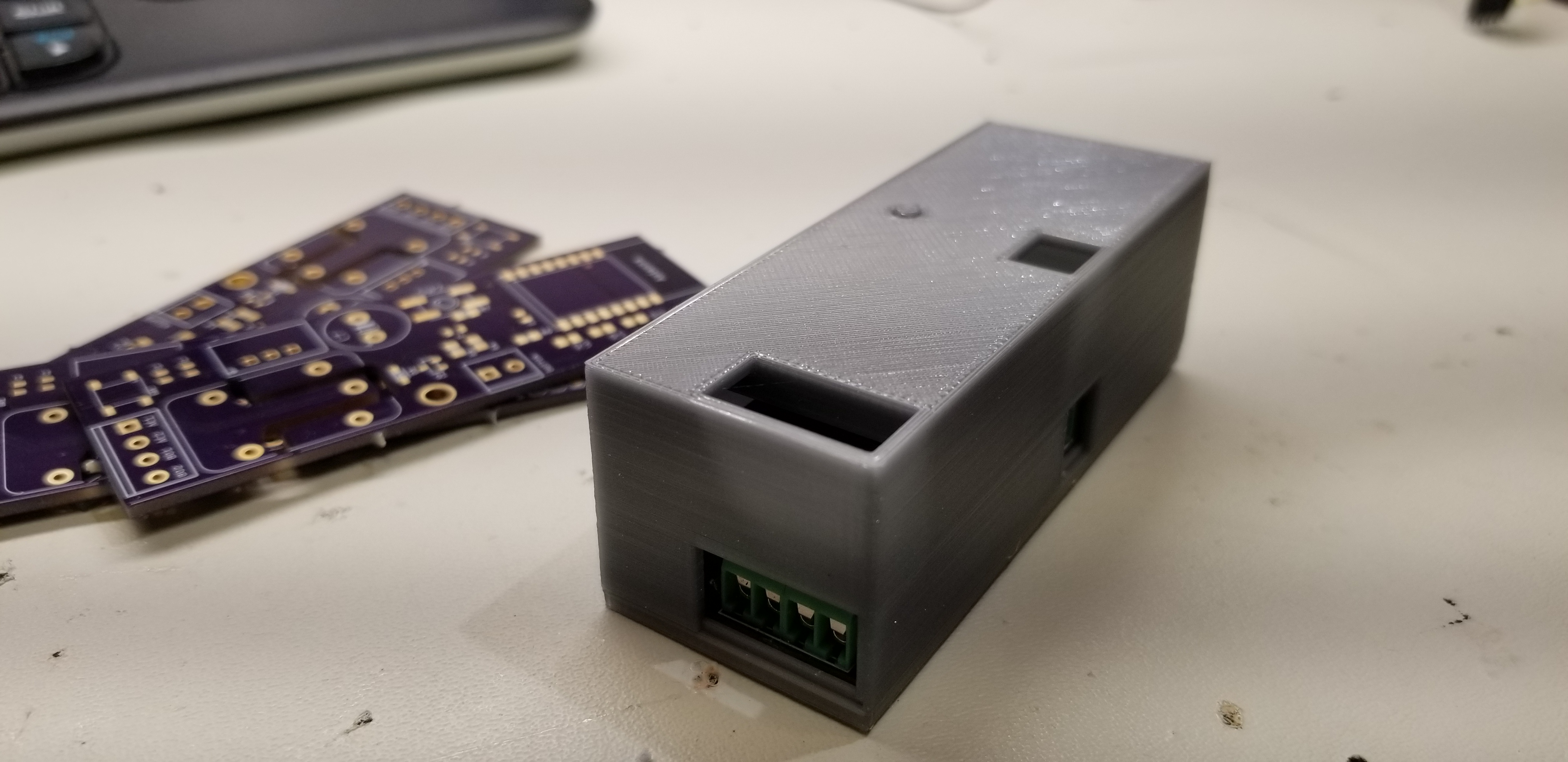
Lastly, I needed to make the solution fit into the existing doorbell cover, given the choices in MCU, this was super easy, I even designed and printed an enclosure for the new PCB and it all fits nicely into the existing doorbell cover, nobody would ever know our doorbell has gained some fancy new features. I'm not an expert in 3D modeling and I've only been using Fusion 360 for a few weeks now, but I think this case turned out good. I even spent the time to build in an external button solution to activate the tactile reset switch on the PCB.


Board before adding screw terminals.

Overall, I'm quite happy with this solution and it's been working without fail for a few weeks now. Every time someone rings the doorbell, the nice doorbell MP3 plays on the selected Sonos speakers around my house and I get a nice SMS message on my phone, perfect! As always, you can find all the artifacts related to this project on my GitHub repo for the project.


Tagged as: , No Comments
14Feb/190

Model the behavior you seek from others…

Not all projects are incredibly complex builds, technically challenging, or innovative in their outcomes. This is one of those projects, however, it's probably one of the few projects that I'll remember for the rest of my life. Being a maker is an amazing and enjoyable hobby for me, it is incredibly satisfying intellectually and allows what modicum of creativity I have to flourish. But this project, it's really special and for none of those reasons.

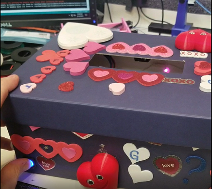
I began this project last week (February 6th, 2019) because my son, who is currently in the 2nd grade, had one of those typical encounters with a schoolmate who was so kind as to inform my son he had no chance of winning the Valentine's box competition in their class. My son is an incredibly smart, caring, quiet kid, he doesn't have a mean-spirited bone in his entire body. I just couldn't sit by and allow him to believe less in himself because a friend told him he wasn't good enough. That's how this project began and it's also why this project is so special to me. I was able to leverage my maker skills to help "amp" up my son's Valentine's Day box and in doing so, hopefully, show him that you can do anything you set your mind to (if you work hard to achieve it). It was so much fun working with him on this project and watching him learn about the different aspects of "amping" up his box. He loves being able to dream up something and have our 3D printer print a tangible version of whatever he dreamed up.

The first step was creating a 3D printed heart that holds 5mm LEDs. I embellished it a bit with voids that I filled with clear epoxy in the hope that it would act as a light pipe. I am quite pleased with the results, I think the thinness of the first layer allows plenty of the LED light to show and the epoxy acted as a solid base for the thin first layer. The next step was sound! I wanted the box to be dynamic and engaging for him and his friends as they exchanged Valentine's Day cards. I landed on using a simple "beam break" style sensor arrangement on the top. This would allow me to trigger any sounds or LED animations based on someone dropping a card in the box; simple and works perfectly. As for the sound, I had previously purchased a Music Maker FeatherWing from Adafruit, so I decided to use that and a Feather M0 MCU for the brains and voice of this project. All that was left on this project was lots of hot glue, some electrical tape, lots of soldering, and finding some music or sound clips...

I haven't heard yet today if my son won any awards or had a chance to learn how his friends responded, but it really doesn't matter. This project was for my son, I wanted to model the behavior I sought in him, never let anyone tell you that you can't or are not good enough, and always take the high road, don't ever think you can make yourself feel better by making others feel worse.


As always, you can find all the project-related files, data, images, etc. on my GitHub repository for this project.

9Feb/160

Homesteading, here I come!

OLYMPUS DIGITAL CAMERA

My wife and I purchased a new home back in June of 2015 and were blessed enough to get a wonderful home (that needed some serious love) and an acre of land in a corner lot surrounded by horse farms. It's an amazing home, mostly because my wife has made it such, but we hadn't really leveraged the outdoors too much. Well, that's all going to change as soon as spring hits. We have big plans for making the most of the land we have been blessed with and I'm excited for the inevitable journey it will become. Go over to www.jnhomestead.com and follow our journey.

I put this blog together to capture all the things I've tried, learned and failed at so that my children could someday learn even more about who their father was and how life is really about living, loving and learning.

My wife and I are going to share our homesteading journey but didn't want to individually blog about it on our personal blogs, so I set up a new site just for our homesteading journey. A site that friends, family and the occasional internet wanderer could read, perhaps enjoy and most importantly learn from.

My mantra is: "Knowledge should be uncompromisingly sought after and freely given away."


5Nov/150

Tactial Simplex Repeater For 2M HAM Radio Operators

Cell Phone TowerBeing a technology geek for me doesn't stop at writing code or hacking gadgets, it extends to even communications and specifically RF (Radio Frequencies). I'm a licensed HAM radio opeartor and have been for some time now. It's true that I love electronics but dang I hate that they require support from a fragile supply of electrons from the wall. When it comes to HAM radio and it's historical use as emergency communications for our nation, I wanted to build something that would allow my small 2M HTs to communicate over wider distances and be free from mains power. I wanted something portable, tactial, that I could use anywhere anytime I wanted. While this is certaintly not the first tactical simplex repeater built by someone, I think it turned out amazingly and much less expensive than something you would buy off the shelf.

First I had to create set of criteria or goals for the build:

  1. Cheap(ish) cost to build (< $400)
  2. Used for days without intervention
  3. Self contained and portable
  4. Support 2M frequencies
  5. Remotely enabled/disabled
  6. Maximize 2M HT distance
  7. Rugged enough to withstand the outdoors
  8. Ready to use whenever I needed them

Housing

My first idea was to use some Pelican 1300 cases I had laying around, free is always better than not. I also wanted to keep the batteries maintained while in the vehicles (these were portable devices I wanted to keep in each car). Unfortunately as you'll read below the original batteries I wanted to use (always do your math first) didn't provide me with the parameters I needed for talk time so I had to get larger batteries and thus had to ditch the Pelican cases and opted for the fatty .50 caliber ammo cans (not the regular .50 cal cans). These boxes are metal, water/air tight, rugged and cheap.

Power

Unfortunately my first idea was to purchase 12AH 6V batteries which did fit in the pelican boxes but really didn't provide me with enough talk time, I was shooting for 12.5% duty cycle which equates to about 3 hours of transmit time a day and 21 hours of receive time a day. I calculated duty cycle using DC=100*(Time On) / (Time On + Time Off). I figure 3 hours of TX time a day would be suffecient in the case of an emergency but I also wanted to build in some padding just in case. Once I had calculated my duty cycle I needed to calculate the power consumption of my system in both TX and RX states. Using my handy dandy multimeter, I measured the power at RX (idle) to be 110mA and TX to be 1.4A. That means that my average power consumption over 24 hours would be 271mA. With this number is was trival to plug in the values to figure out what sized battery I would need, I used an online calculator that used Peukert's formula for calculating battery life. Ulitmately I decided on a 35AH 12V battery which would give me approximately 37 hours of runtime at 25% discharge (higher discharges ultimately shorten the life of the battery).

Now the task was to figure out how to replinish the juice in my battery, solar is the way and I settled on a Renogy 30W solar panel. Why you ask, well the panel gives me about 1.3A of power on a sunny day, it's somewhat portable, and Renogy sells great quality solar panels for outdoors.

Power Conversions

As with any solar setup, I had to purchase a solar charger to ensure my battery was correctly charged by the panel and ensure the battery was never overcharged. The solar charger I picked up is the Renogy 30A model, more than enough for a single 30W solar panel configuration. The solar charger also has another nice feature which is that it has load terminals. These terminals allow you to hook up your load (the radio gear in my case) and the charger will automatically disconnect the load if the battery voltage drops too low. This particular model solar charger has about 20 different modes you can select for how it manipulates the load terminal (dusk till done, dusk then xx hours, etc).

With the battery and solar system figured out, I had a few more power conversions I needed to address. Namely the radio which has a max input voltage of ~8.4v, the repeater module accepted a wide range of voltages so our 12v battery voltage was fine for it. As for the radio, I had to purchase a buck converter that would effeciently drop the 12v to the ~8.4v required. I found a cheap one on Amazon which was rated for way more power than the radio would need and was manually adjustable so I could easily dial it to the voltage I required. I hacked up a battery eliminator cord for my radio and ran it directly to my buck converter, works perfectly and never gets even warm to the touch at 8W TX on the radio.

Radio Gear

As for the radio (the most important part actually), I decided on a Baofeng, more specifically the BF-F9 V2+ HP 8Watt Tri-Power HT. I wanted to keep costs down, but also wanted the little bit extra TX power this version gave over the cheaper 5W models available. Baofeng is a manufacturer of cheap HAM radios (but have been surprisingly reliable) but costs containment is a goal so no Yeasu HTs or the like were an option. The decision of which simplex repeater (voice recorder and playback device) was easy, there are not many available from reputable supplieers so the ADS-SR1 from Argent Systems was my choice. It had great specifications and was easily managed remotely using DTMF tones. Fit all the criteria I needed.

The last tiddly bit was the connectors for the radio and the antenna selection. A female SMA connection is more common now that these chineese radio manufactures are using them but eBay was still the only source I could find that had them with various other ends. I chose a female SMA to BNC pigtail. The reason for BNC was simply because the antenna I wanted came in a BNC type connector and I really wanted a stronger attachment point that SMA. I wanted as good gain as I could but also try to maintain my goal of portability. It took me several days to find what I was looking for and I finally decided upon the MFJ-1714 telescoping antenna from MFJ. It's got great gain and works better for this setup than any others I could find. It collapses down and can easily fit inside the can but reaches ~40" when fully extracted. I'm really loving this antenna!

Build

The build on this project was actually lots of fun. I was able to leverage my favorite tool, the hand riveter which I used to build a cradle for the battery which prevents it from moving around and damaging the other components. Other than that, it was a pretty simple process of drilling a couple of holes, one for the antenna and the other for the 12V cigarette lighter socket which is how the solar panel plugs into the box. A box of super strong Velcro from Lowes finished off my build, I simply secured the radio and other components to the sides of the interior. I'll post some pictures of the build later this week once I get a chance to get my new shack setup.

Final Thoughts

I've tested the range of this repeater on 147Mhz with it sitting on the top of my house. I'm able to clearly transmit and receive on a Waesu 5W HT from about 8 miles away with the repeater sitting on my back patio, elevation to remove any obstructions would clearly extend the range significantly but that's for another day. Overall I'm very happy with the build and the results, once I have an opportunity to get this thing higher in the air and perform a more extensive range test, I'll update this post.

6Aug/150

DSC Alarm + Envisalink3 + DSCServer + SONOS = Alarm Announcements!

Electricty Chaos

Image courtesy of antpkr at FreeDigitalPhotos.net

Long title and a large degree of entropy? Nah! This is a system that was built in layers but the components are largely used and fairly niche in their use. I've just decided that I'd use them to provide something even more niche, an alarm zone announcer for my house. Sounds cool to you then keep on reader, otherwise go back to your other boring business reading materials...

This all started when my wife and I decided to buy our "forever" home. A wonderful home on a bit of land in the city where our families lived, thus, the "forever" home label. The problem with our forever home is that it's a 2 and 1/2 story home and I'm always concerned with security, mainly the security of my family while we are home. I could really care less about someone stealing my junk as long as my family is safe. I wanted a way to ensure we would be aware if someone entered our home while we were home, awake or sleeping.

Long story short, I purchase a DSC Powerseries PC1864 system and the wireless sensors to put on each door and window. After we moved in and I got the system operational I realized the hectic process of leaving each morning would likely result in the alarm not getting armed so I sought out a way to remotely view and control it. I found the Envisalink3 card for my system. Nice little tool but the software is massively lacking in both features and security (no SSL for goodness sakes). That led me to the DSCServer software written for Android and Linux by MikeP. Great product and was the last piece to the puzzle for me....

Well, that was until I noticed my in-laws ADT system had a cool feature which would verbalize the zones that get opened...I loved that so much more than the beep...beep...beep my system made when a door was opened while the alarm was disarmed. Searching the interwebs left me empty, nothing was available to plug into my security system to give me that same awesome feature, I guess I'd have to roll my own. That's where my SONOS system (a total of 5 speakers) comes into play, it's got a wonderful full-featured API and it only took a few minutes to find a full-featured PHP library to control my system.

I leveraged the same raspberry pi that I was using for DSCServer to run apache2 and fixed up a nice PHP page which would announce which zone was opened based on a query string parameter passed to it. I then added an action for each zone in DSCServer to call the URL with the correct query string value for each zone. Volia! My SONOS speakers will quickly pause, a nice British lady will announce which zone was opened, and then the speaker goes back to whatever it was doing before the announcement.

I'm hard to please and this solution while dependent on layers of technology, works exceedingly well. There is a 2-4 second delay in the announcement which I'm strongly suspecting is the lack of power on my Raspberry Pi running DSCServer. I'm going to upgrade it to a Raspberry Pi 2 and see if I can reduce the lag time some. Otherwise, this project is complete.

As always, I believe knowledge should be free and freely shared. The PHP page I wrote is attached to this post for all to use. I've also linked below to the components I used (I'm not endorsing any retailer, it's just where I purchased).

DSC Powerseries Alarm & Envisalink3

DSCServer Software For Envisalink3

SONOS Speakers (I have several Play3s and Play1s)

SONOS PHP Library

zoneOpened
Title: zoneOpened (1084 clicks)
Caption:
Filename: zoneopened.zip
Size: 1 KB