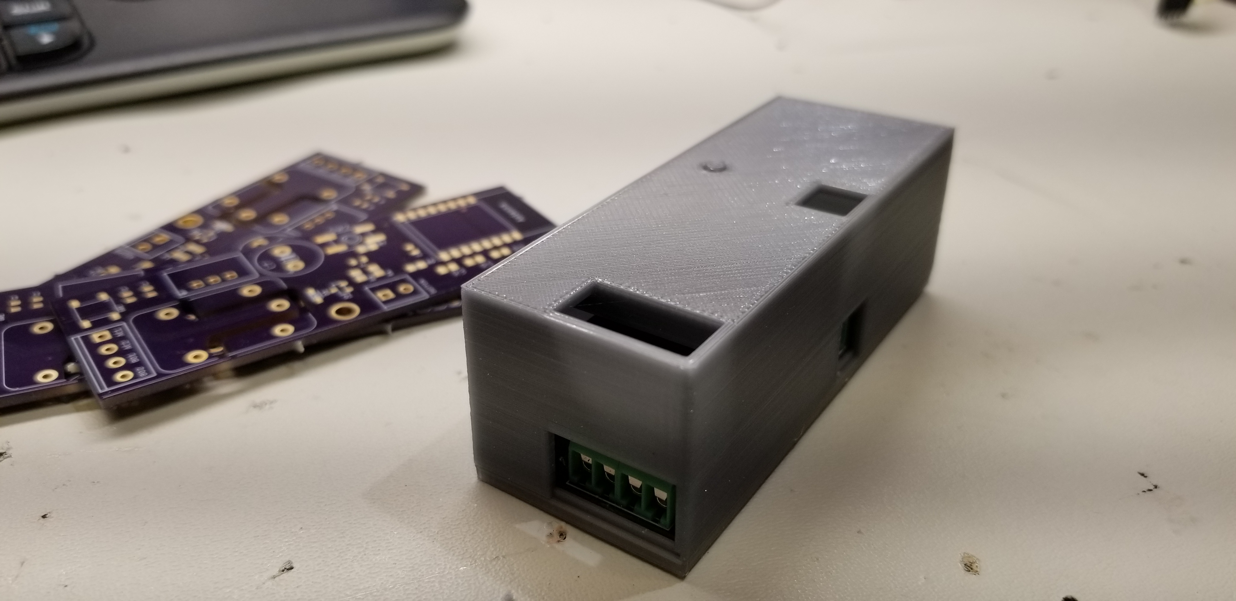
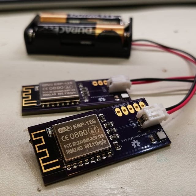
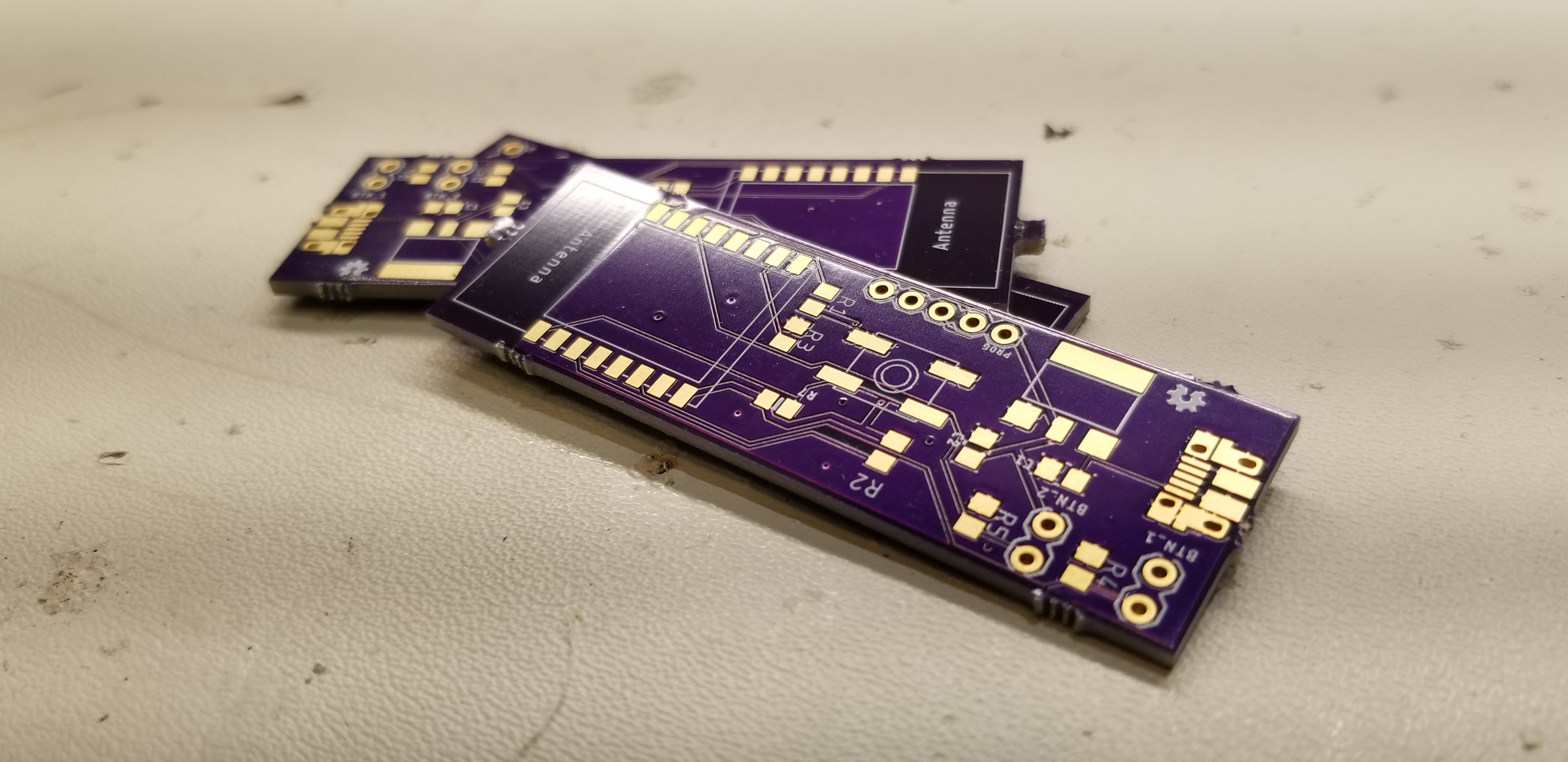
Lifelong Learning Knowledge should be uncompromisingly sought after and freely given away.

8Mar/190

A simple dual MQTT button…

I seem to be on a roll lately with these ESP8266 based projects, but they are so fun and useful, it's not difficult to identify new uses. This project originated from another project I just completed, building my own solder fume extractor. I wanted an easy way to turn the fume extractor on and off as well as having a timer turn it off after a few hours (in case I forget to turn it off). I immediately thought of a USB-powered MQTT "button" that would toggle the fume extractor on and off. But hey, if I was going to have this feature for my fume extractor and bother with incorporating it into my HASS.IO server, why not add another button and allow it to toggle two switches. I could use the other for my soldering iron, which sadly does not have an automatic shutoff built-in. And if they are both accessible to my HASS.IO server, why not automate and coordinate them? But first...

As with all of my projects, I listed the problem(s) I was trying to solve and my requirements for a solution.

Problems I wanted to solve:

  1. Eliminate the need to plug in and unplug the fan power cord on the fume extractor every time I want to use it
  2. I often forget to turn on the fume extractor when soldering
  3. Shut off the extractor after a few hours (in case I forget) or when the soldering iron is turned off
  4. I have been known to forget to turn off my soldering iron

So, four primary problems to solve. What are my requirements?

  1. Switch or button within easy reach while sitting at my lab desk
  2. Leverage HASS.IO to control the Sonoff plug on the extractor and the Sonoff plug on the soldering iron
  3. Not take up any desk space
  4. Use up some of the numerous ESP-12S modules I already had on hand
  5. Have nice large buttons (I love arcade buttons)

Since I knew I wanted to leverage 28MM arcade buttons and I needed two, I started this project with the design of the enclosure. It's silly large because of the arcade buttons, but I planned to mount the whole enclosure under my desk anyhow, so size was less important than my desire to use ARCADE BUTTONS! I only challenge in the build for this enclosure was that I had decided I'd try my hand at mechanical retainers to hold the PCB in place, I ended up exporting the PCB design from EagleCAD into Fusion 360 and building the enclosure around it. The design allows the PCB to be slid into the slot from the back and a small tab holds the PCB in place once it's fully slid into position.

The next task was to design the actual PCB, which was super simple this time. I have already used all of these components andwas able to put this one together in about an hour. Although, in full transparency, I did send the first version off to OSHPark to fabricate only to realize I had put the USB connector on the board backward; speed and quality are always in conflict it seems. With that silly mistake resolved, I was good to go with this step.

The last step was writing the firmware for the ESP8266 and modifying my HASS.IO server settings to add the new button (switches) and automation to trigger the appropriate Sonoff switches when the buttons are pressed. The Arduino code is very straightforward. The modifications to my HASS.IO configuration was a bit tricker, I didn't really want to deal with having the MQTT button query the state of the switch and issues an "ON" or "OFF" command, I just wanted it to "TOGGLE" the switch, regardless of its current state. I ended up figuring out that I could trigger a toggle command on the Sonoff switch based on any published message to the MQTT button topic. What this means is that my automation will trigger anytime any message is published on the MQTT button topic, doah. Sometimes things are just easier than you'd expect. I just had to add a second automation for the second button and test things out.

Testing was great, the only bug I found was that I had swapped the button IO pins on the PCB in firmware. A quick reflash of the ESP8266 with the fixed firmware and it was all good. As soon as the button is pushed for the fume extractor, it comes on, super low latency. Same was true for the second button that controls my soldering station. It was working and working perfectly!

One last enhancement needed to be developed, however. I wanted to automatically turn on the fume extractor when the soldering iron was turned on as well as turn it off when the soldering iron was turned off. However, I wanted to allow independent control of each so I could easily override the automation of the two, thus the two buttons. Doing automation in Home Assistant (HASS.IO) is fairly straightforward, lots of great community articles on how to write them, so no need to poorly attempt to instruct anyone on that here.

Overall, I'm absolutely thrilled with this project, it was incredibly easy to execute on and the reward; it makes me smile each time I get to smash that arcade button and hear the soft whirl of the fume extractor!

As with all my projects, all the artifacts for this project can be found on my GitHub repo for the project here.

4Mar/190

A smarter doorbell (without all the extras)

Automating my home has been a journey I've been on for several years now and at no point in that journey did I feel the necessity for a $200USD  doorbell. Not that I don't see use cases for it or think others couldn't have a compelling use case for them, I, however, could never identify a use case that justified the purchase costs (and potential monthly subscription costs). Not to mention I absolutely hate products that require cloud services to function. There are far too many instances of companies deciding to shutter their cloud offering or otherwise discontinuing the service which most times, leaves the product only useful as a doorstop.

Recently, however, I did find a use case for some improvement in our current doorbell situation. Our doorbell is wired, but it's tough to hear from anywhere but the living room. I tried replacing the doorbell with a newer model that was supposed to be louder and yet it still didn't help. I wanted to be able to hear the doorbell from any room in the house (basement included). I also wanted an SMS or other notification when someone rang the doorbell. What I didn't want was any cloud-connected solution, video or bi-directional audio. I didn't see the use case for those features. I also wanted to keep the aesthetic of our wire doorbell button (I personally do not like the asthenic of most modern "smart" doorbell buttons with cameras and bright blue LEDs).

That's when I started looking for options for purchase, undoubtedly someone shared my same thoughts on the "smart" doorbells and had a solution I could purchase, or at least build from...well, I was wrong. I couldn't find anything that filled the gap between a traditional doorbell system and the ultra-modern camera-enabled doorbell buttons. There were some articles where folks were trying to solve very niche issues with their old-style doorbells but nothing that fit my use case and had a very high WAF (wife approval factor).

So I decided to do what any sensible maker would do, I set off to design and build my own, and this serves as a record of my journey with this project.

First, I sat down and documented what the problem was with the current solution, a simple hard-wired doorbell where the actual doorbell is mounted in the stairwell leading upstairs and is very difficult to hear (I wasn't about to attempt to relocate it, but I did investigate that option first). There are two primary problems with the current solution.

  1. It's impossible to hear the doorbell unless you are standing in the stairwell.
  2. There are no modern-style digital notifications of the doorbell being rung.

So, what then are my requirements for a new solution?

  1. Keeps the use of the existing doorbell, wiring, and doorbell button.
  2. Can communicate with my HASS.IO server (MQTT preferred)
  3. Does not prevent the doorbell from working if the internet, my network, or my HASS.IO server is down. Works like an old-school doorbell should work when all else fails.
  4. Requires no batteries
  5. Fits inside the existing doorbell cover and/or outlet

Now that I felt like I knew what the problem was and I had a good set of requirements for a new solution, I could start my design. The first requirement that I felt I needed to tackle was the requirement to run off the existing 16V AC power the current doorbell leverages, and thus eliminates the need for any batteries. I was surprised by the search results I found when searching for similar DIY solutions, the way some folks were going about attempting to rectify and leverage the 16V AC blew my mind...I spent a few days researching best practice and standard designs for basic AC/DC rectification and landed on a design I felt would suit my needs. I ended up testing the design and was quite pleased with the results (and lack of ripple). I found this article particularly helpful in identifying the size/value of the filtering capacitor to use in my design. I tested the ripple in my design and included the results in my GitHub repo.

Screen Capture

Now that I knew that I could get good clean 3.3V power from the 16V AC power already available (and reuse that wiring), I needed to ensure I could communicate with my HASS.IO server and thus satisfy that requirement as well as the ability to have other (SMS, Email, etc.) notifications when the doorbell is rung. Given my recent development projects, all have revolved around the ESP8266 MCU; it was a no brainer to decide it would fit the bill here as well, it's small, powerful and has relatively low power consumption.


MCU Relay Trigger Detect

The last significant requirement to design toward was the need for the solution to not interfere with normal doorbell operation when the complex pyramid of dependencies failed. It needed to ring just as it would have thirty years ago without all this newfangled technology existed. I pondered my options for a few days before landing on the idea to use a standard mechanical relay. I will rectify the 16V AC down to 3.3V DC which will power the ESP8266. I'll also use that same 3.3V DC to trigger the relay using the existing doorbell button, although I will replace the AC light inside the button with an LED which is obviously not an issue if you don't have a fancy doorbell button with a light. In order to detect that the button was pushed and to trigger the MQTT message to HASS.IO, I'll assign an IO pin from the ESP8266 to monitor the state of the button, when it detects the button going HIGH (someone pushed the button and energized the relay to ring the doorbell), it'll send the appropriate MQTT message. I'll allow HASS.IO automation to perform notifications, and most importantly, play a "door-bell" sound effect on all my home Sonos speakers, ensuring we hear the doorbell. This design is how I satisfy the requirement that the doorbell works just as it did 30 years ago. As long as there is AC power, the doorbell will work, even if the "smart" features don't.


Lastly, I needed to make the solution fit into the existing doorbell cover, given the choices in MCU, this was super easy, I even designed and printed an enclosure for the new PCB and it all fits nicely into the existing doorbell cover, nobody would ever know our doorbell has gained some fancy new features. I'm not an expert in 3D modeling and I've only been using Fusion 360 for a few weeks now, but I think this case turned out good. I even spent the time to build in an external button solution to activate the tactile reset switch on the PCB.


Board before adding screw terminals.

Overall, I'm quite happy with this solution and it's been working without fail for a few weeks now. Every time someone rings the doorbell, the nice doorbell MP3 plays on the selected Sonos speakers around my house and I get a nice SMS message on my phone, perfect! As always, you can find all the artifacts related to this project on my GitHub repo for the project.


Tagged as: , No Comments
21Jan/190

Battery Powered IOT Filament Storage Sensor

Filament Sensor BoardsI finally finished what I'd call a satisfactory version of my filament sensors. I've wanted an affordable, accurate, and geeky way to monitor the humidity inside the storage boxes I use to store all my 3D printing filament and couldn't find anything on the market that met my needs. So, I built my own and here they are.

Before setting off to build my solution, I had to identify my requirements for them:

  1. It had to be battery powered
  2. The batteries had to last at least six months
  3. It had to log the humidity and temperature to my existing HASS.IO home automation server
  4. It had to be cheap (ideally less than $15 USD)
  5. It had to be fairly accurate in its measurements of temperature and humidity

I've been a big fan of the ESP8266 for a long time and this project was a good fit for that platform as I know how to work with them, they are cheap, and I already had a large stock of them! The only issue with the ESP8266 is how much energy it consumes, an average of 120mA when transmitting and 56mA when receiving, that WiFi is a killer! Luckily there are sleep modes for the ESP, especially curious to me was the deep sleep mode, at 3.3v the ESP would consume about .3mA which is way more battery friendly. Putting the ESP into a deep sleep for the majority of the time would satisfy the requirement that it run from AA batteries and last at least six months (actually calculated it to be about 240 days)! If more time was required for your requirements, you could always go with four AA batteries to double the capacity and time between swapping them out.

The next requirement was that it log the sensor data to my HASS.IO server, that was easy to accomplish as the ESP is WiFi enabled and this brilliant guy wrote an MQTT library for Arduino so I just worked with it to publish the sensor data, easy enough.

Ensuring the sensor I used was accurate, fairly cheap, and low energy was easy as well. I initially built this to leverage the BME280 sensor but was only able to get that chip in a module form which I didn't like. I tried reflowing the BME280 to a PCB but failed fantastically numerous times. I found a great deal on some SI7021 sensors that seemed to be a really nice IC for detecting the humidity with great accuracy and was temperature compensating. The SI7021 is also an I2C device and Adafruit had already built a library for it. Done deal!

And the cost? Well, I wanted an inexpensive solution and I feel this fits the bill. I was able to build three of these at $9.15 USD each. In any sort of quantity, these would be far cheaper!

And lastly, I wanted to make sure I had the hourly temperature and humidity data available in my HASS.IO dashboard with historical charting, which works wonderfully as you can see below:

While not really a requirement, no project would be complete without a custom printed enclosure. I'm far from being good with Fusion 360 and 3D modeling but I gave it a go and came up with a functional case for the sensor (files are available on Thingiverse.com).


As always, you can find all the files, pictures and other artifacts related to this project on my GitHub page for this project.