Lifelong Learning Knowledge should be uncompromisingly sought after and freely given away.

11Feb/130

Great read for battery powered projects!

iStock_000015833126XSmallI've had many a project lately that needed to use batteries rather than being powered from the mains. I've been reading lots lately about saving power in AVR chips and general concepts for power conservation in my projects. It's made me a better engineer in general and I think all my future projects will benefit from the knowledge regardless of their power source. During all my research I did stumble upon this article that I thought would be useful to the masses and thought I'd share it with everyone.

http://www.sparkfun.com/tutorials/309


Filed under: AVR, Electronics No Comments
25Oct/100

ATTiny13A Powered Jack-O-Lantern

2010 AVR Jack-O-Lnatern

This year's indoor AVR powered jack-o-lantern

So I was waiting for this time of year when I first built my "Fake-fire LED" boards last year and now it's finally here!

I've been running this jack-o-lantern for about 20 days now (this board is running off 3xAA alkaline batteries) and the LEDs seem to be doing just fine, the effect is fantastic and I couldn't be happier with the new power-saving firmware I put on the AVR to help with battery life. I keep this one indoors but I plan on putting another board in a real pumpkin I'm carving tonight and putting it outside, I think the effect will be even better with a carved pumpkin. Can't wait! I'll update this post with pictures of it when it's done!

I highly recommend this project, it's a fantastic way to get started with understanding AVRs and the possible power saving modes, I've learned so much from this project and it's super quick to put together on protoboard...

For next year's version, I'll be addressing that pesky constant current draw for the photocell to extend the battery life even more (recommendations are most welcomed). I've posted high-resolution schematics below but you can find all the source code and eagle files in the zip file attached to this post.

Have a Safe and Happy Halloween everyone!

Close up of the tiny board and battery holder. Next year I plan on hiding this better.

Here I've just run the photocell out the back of the plastic jack-o-lantern.

Eagle Schematic for my board.
Jack-O-Latern
Title: Jack-O-Latern (1411 clicks)
Caption:
Filename: jack-o-latern.zip
Size: 34 KB

Jack-O-Latern
Title: Jack-O-Latern (1411 clicks)
Caption:
Filename: jack-o-latern.zip
Size: 34 KB

Filed under: AVR, Electronics No Comments
1Aug/100

IKEA Lampan RGB LED Light

A few months ago, I saw this blog and video. The gentlemen had hacked a Lampan light from IKEA with LEDs, I was immediately enamored with the idea of building it and giving a few of them to my young nieces for Christmas. I figured they'd be far more excited about a one-of-a-kind light than a few more dolls in the 'ole toy box.

I also wanted to further my design knowledge of PCBs as well as better understand using PWM in AVRs, until this point I'd really only played with my Arduino and a few ATTiny13s. I quickly came up with the following design to suite my requirements.

My Requirements:
1. AVR with at least 3 PWM channels. (I used the ATTiny2313)
2. Super bright RGB LEDs.
3. Warm white light for normal use, not the normal blue hued white LEDs.
4. In-circuit programmable design.
5. Fit in the base of an IKEA Lampan.
6. UL approved power source.

First Version of my Lampan RGB LED PCB

Lampan RGB LED PCB

I used quite a few surface mounted components to get the size down.

The lamp uses a single momentary button to switch (you need special drill bits to drill the hole in this thin plastic, trust me, check Harbor Freight for them!) between the colors and the two color mixing modes (one, I jokingly refer to as "light switch rave" and the other a slow color changing mode). My wife absolutely hates the blue hue of normal LEDs, so I knew my design would have to incorporate a few warm white LEDs in addition to the RGB LEDs, thus the 3 warm white LEDs in the middle of the board.

I got the 5mm RGB LEDs from here, highly recommended! And yes, I did use a single resistor for each color, typically a no-no in design, but the trade-off was worth it for me. I wasn't overly concerned with exact color intensity from each LED.

Anyhow, this was a fun build and Christmas was a hit, the family loved them. I've attached the Eagle schematic and AVR Studio files to the post if anyone is more interested in the design.

Lampan RGB Firmware
Title: LampanRGBDriver (4091 clicks)
Caption: Lampan RGB Firmware
Filename: lampanrgbdriver.zip
Size: 3 KB
Lampan Eagle Schematic and Board Files
Title: LampanRGBLedSchematic (1238 clicks)
Caption: Lampan Eagle Schematic and Board Files
Filename: lampanrgbledschematic.zip
Size: 34 KB

Lampan Eagle Schematic and Board Files
Title: LampanRGBLedSchematic (1238 clicks)
Caption: Lampan Eagle Schematic and Board Files
Filename: lampanrgbledschematic.zip
Size: 34 KB
Lampan RGB Firmware
Title: LampanRGBDriver (4091 clicks)
Caption: Lampan RGB Firmware
Filename: lampanrgbdriver.zip
Size: 3 KB

30Jul/100

Nursery Room Temperature Monitor

Temperature Monitor Indicating it's too warm

Temperature Monitor Indicating it's too warm

Let me start by saying I found out a few weeks ago that I'm going to be a father. This is my first child and as you can imagine I'm filled with excitement and nervous energy. Both my wife and I both agreed that we wouldn't start actual preparations for the coming baby until the 12th week to ensure all was well (1 in 4 pregnancies end in miscarriage). I just couldn't sit still and wait, I started reading about what to expect, how to care for a newborn, and so forth.

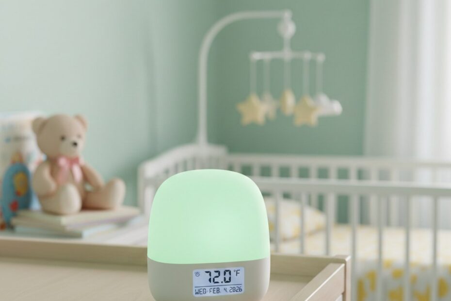
It was while I was reading about SIDS (sudden infant death syndrome) that I saw a few articles discussing the proper temperature for a nursery to help prevent the SIDS. The articles all agreed that cooler was better, ideally between 64 and 74 degrees Fahrenheit.

I was immediately struck by the idea of creating a visual indicator to allow both my wife and I to easily ensure the room was within this range! I grabbed up my Maker's Notebook and starting drawing what I was envisioning. What did it look like, you ask? Keep reading, you'll soon be rewarded with the answers you seek!

My idea was to utilize a diffused RGB LED, an analog temperature sensor (really wanted to expand my working knowledge of the ADC on AVRs) and a frosted glass sphere to create a highly visible temperature indicator. I quickly sorted through my parts bins and found most of what I would need. A quick search on eBay and a short drive to Lowe's provided the rest.

Here's what you'll need to build one yourself:
1. Wooden base, use your imagination.
2. Frosted glass light shade.
3. LM335 Analog Temp Sensor
4. Atmel ATTiny45/85 micro and appropriate socket.
5. Common anode RGB LED (doesn't have to be diffused, you can do that yourself with sandpaper).
6. Two (82 ohm) , one (150 ohm), one (10k ohm) and one (2.2k) 1/4 watt resistors.
7. A 10k potentiometer.
8. One (.1uF) capacitor.
9. A power source. I used an old Netgear router power supply. 5V regulated output at 2.0A.
10. Some wire, heat shrink tubing, Velcro and appropriate soldering equipment.
11. Firmware and schematic.

I typically breadboard all my designs then move them to PCBs once I've worked out all the kinks, but I had recently purchased a mini drill-press and PCB development kit from Jameco and decided the simplicity of this design would allow me to go directly to a DIY PCB (it also gave me an excuse to try my newHad to calibrate the temp sensor using the 10k pot and my Fluke with attached thermocouple.

Once done, I sat down and wrote up the firmware using AVR Studio 4. After a few more hours, I was all set to try it out. And TADAAA! A fully functioning accurate temperature indicator for the new nursery. I'll paint the wooden base once we decide on colors for the nursery!

A few equations that made my life easier and an excellent article to extend your understanding of the ADC in any AVR:
AVR Freaks (ADC For Newbies)
Convert Kelvin to Fahrenheit

EagleSchematic
Title: EagleSchematic (1351 clicks)
Caption:
Filename: eagleschematic.zip
Size: 22 KB
NuseryRoomTempMonitorFirmware
Title: NuseryRoomTempMonitorFirmware (834 clicks)
Caption:
Filename: nuseryroomtempmonitorfirmware.zip
Size: 3 KB

NuseryRoomTempMonitorFirmware
Title: NuseryRoomTempMonitorFirmware (834 clicks)
Caption:
Filename: nuseryroomtempmonitorfirmware.zip
Size: 3 KB
EagleSchematic
Title: EagleSchematic (1351 clicks)
Caption:
Filename: eagleschematic.zip
Size: 22 KB

Filed under: AVR, Electronics No Comments
6Dec/090

Finally Got My FakeFire LED PCB Boards Done

ATTINY13A Fake Fire LEDA while back I wrote about a neat project that I had read about where a couple of LEDs and an ATTINY13 had been used to simulate the flicker flame of a candle or fire. I built a prototype and quickly realized that project deserved more of my attention, I spent the next couple of days tweaking the design and code to come up with this! My primary design focus was battery life and I've been running this board with 3 standard AA batteries for nearly 2 months. Good enough for me! This design incorporates a photocell to turn the LEDs off during light hours and a deep sleep mode for the AVR when the LEDs are not illuminated. A watchdog timer triggers the AVR to wake up and sample the photocell to decide if it's dark enough to start illuminating the LEDs. I've included the Eagle schematic and board files in addition the the AVR C code and high-res pictures in the attached zip.

ATTINY13A LED Fake Fire

ATTINY13A Fake Fire LED

Fake Fire PCB Zip File
Title: Fake Fire PCB (2021 clicks)
Caption: Fake Fire PCB Zip File
Filename: fakefirepcb.zip
Size: 3 MB

Fake Fire PCB Zip File
Title: Fake Fire PCB (2021 clicks)
Caption: Fake Fire PCB Zip File
Filename: fakefirepcb.zip
Size: 3 MB

1Dec/090

My Ice Tube Clock from Adafruit Industries

Ice Tube Clock from Adafruit Industries

image curtesy of Adafruit Industries

I've always loved when things old and new come together to form something new and interesting. I think that's the best way to describe my new Ice Tube clock from Adafruit Industries. They've managed to mix an old eastern bloc VFD (vacuum fluorescent display) with modern electronics to form a wonderful desktop clock. Not only is this clock a fantastic conversation piece it's highlighting an amazing piece of electronic history, the VFD.

I actually decided to get this kit for myself as I've been researching building my own desktop clock using 7-segment LED displays. When I stumbled upon this kit, I had to have it. So for now, I've put my design on the back-seat and settled on hacking this thing! Stay tuned for more...

Tagged as: No Comments