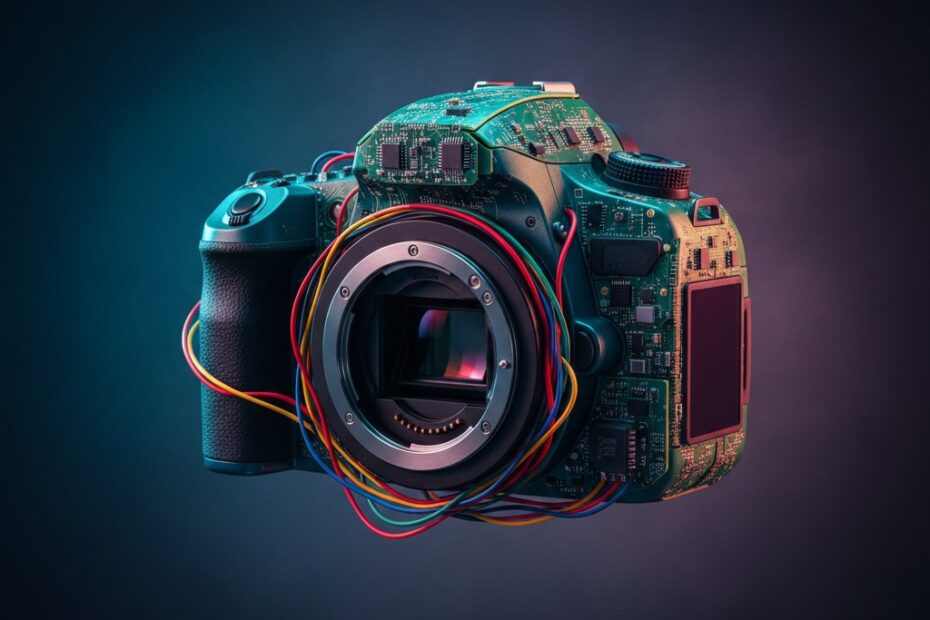
Homemade Blinky Christmas Ornaments
Last year I decided to jazz up our family Christmas cards with LED power, inspired by this article. While I was totally happy with the cards I sent out, I was wanting something a bit more this year so I've decided to take it one step further and create Christmas ornaments for our family that will be sent with this year's Christmas cards.
I had a few criteria that drove my design for the ornament not to mention I had a very short timeframe so simplicity was important:
1. Have the same shape as a typical Christmas ornament (it is an ornament after all).
2. Lots of LEDs, folks in my family love LED blinky things.
3. Battery powered and last as long as possible on battery.
4. Hackable. I wanted the board to be easily hacked by family and friends that were so inclined.
5. Maximize the visual appearance of the front of the board (no through-hole components), I was also going to put a Christmas message on the front in silkscreen.
After a few hours piecing together the schematic, I was pretty happy with the reChristmasOrnamentsults. Ironically when I went to start the board design I ran into a simple but problematic issue of how to evenly place the LEDs on the round board, being the true geek that I am, I wrote a C# app which you can see in the ZIP file attached to this post. It gave me the x and y coordinates for each LED given the radius, origin and degree. Being late at night when I finally got around to laying out the board, this was a true life saver!
Once I had the LEDs placed, I decided to go back and add some blue and white LEDs on the neck of the board to enhance the "blinky" factor. Skip ahead 4 more hours and I had finished the board layout. I always give myself a day or two after the board is done before I come back to it and QA the layout, saves me tons of time staring at a problem and not seeing it! My QA found several issues and once resolved I sent it off to the boys over at BatchPCB.com for fabrication.
Fabrication typically takes three weeks or more but I was nicely surprised when my boards shipped after only 7 days and being the OCD type I am, I had to assembly one of the boards as soon as they came in the mail. It took me about 3 hours to assemble the first board, I was being overly cautious and deliberate in each solder and relearning how to use my hot air rework station. The total time for the first board included soldering up my homemade ATMega TQFP programming board which I used to burn the Arduino Uno boot loader onto the ATMega chips I had leftover from a previous project. I'll post about it in more detail later, I have a few minor tweaks to make to the design before I think I'll be totally happy with it, but it served me well for this project.
With the boot loader loaded, the final test would be attempting to load a sketch on it using my FTDI cable. To my total elation, it loaded the sketch without issue and my blinky utopia began! I was absolutely filled with joy when those LEDs started blinking away, who knew something so trivial could be so satisfying. I learned a lot with this project and I gained some important confidence in my design and layout skills which should serve me well with my next project.
As for battery life, I've adjusted some of the animations so that I could eliminate having all the LEDs on for extended periods of time and found that I was able to leave the ornament on constantly and the batteries died (the board actually froze) after about 40 hours. I thought about putting in a sleep mode after 6 hours of use or something but I think I'll pass and allow the user to just remember to shut them off, heck those inclined could do it themselves!
Well, I'm giving out the ornaments on Thursday (Thanksgiving) so that friends and family can enjoy them on their trees this holiday season, I sure do hope they enjoy them as much as I enjoyed building and designing them! Check out a video of them in action below!
Arduino Clone Powered RGB Keyboard Light
I recently remodeled my office as I'll be working from home full-time starting in March, it's amazing what you can do with $1k dollars at Ikea! Anyhow, love my office setup, especially my desk but I had one nagging issue, I couldn't see the keys of my keyboard easily when the office was dark. My wife subltly suggested I get some sort of light to put underneath my desk to illuminate the keyboard. Ah, how I love my wife and her fantastic ideas...
Obviously, I wouldn't settle for some store bought device, I'm a self-declared "Maker" after all! After several days of tossing around ideas in my head, I decided it'd be super neato to have an RGB LED board under my desk and have it connected and powered by my computer. I'd then have some software sit in my system tray so I could control the board (colors and etc). Yeah, that's exactly what I needed!
So, yesterday I decided I'd set out to build it with only the parts I had on hand, I'm having a baby and thusly on a very restricted hobby budget!
Since I'd be etching the board myself, I knew I'd use through hole components to make life easier and I centered the project around an ATMega328 since I wanted to use serial communication with my PC and the quickest path was to use Arduino programming language (using a FTDI cable). I also wanted to utilize some 5mm common annode RGB leds I had on hand from a previous project but I wanted at least 5 to make sure I had good illumination on the keyboard and I wanted to use PWM to allow color mixing...well, a few 2907A transistors and a dozen or more resistors later I had a schematic I could be proud of.

Eagle Board Layout for my RGB keyboard light
The layout of the board was easy, I had a 3"x4" single sided copper photoetch board, so I laid all my components out to fit the whole board (I didn't want to cut it). I also learned the hard way that small traces are a pain in the butt when etching your own boards so I set my traces to 24mil, genrously large enough to not create issues during the etch. I didn't get any pictures of the board before it was mounted, sorry. You can always refer to the board image in the zip file attached to this post.
Once I had soldered all my components on the board, I threw in an ATMega328 micro that already had the Arduino bootloaded burned. Hooked up my FTDI cable and my test sketch worked flawlessly. Whew, nothing like going from concept to finished board with no testing to get the nerves going!
With the board testing out good, I set about coding up a C# app to control it. I had previously worked with serial comunications using C# and an Arduino which I talked about in this post so the C# code was really more about figuring out how to get a sys-tray app working as I wanted than worrying with the serial communications. I think it took me about 2 hours from start to finish to get things to a point I was happy with (nice and quick not nice and neat). I'm a developer by trade so I knew all along this would be the easiest part for me.
Well, a very quick project for me, one I'm quite proud of actually. As always I've attached high resolution pictures, eagle schematics, Arduino sketch and this time the Visual Studio solution in the zip below.
Drop me a note if you have any questions about this project, I think it's a fun and easy project for folks to test out thier etching and coding skillz!
Check out the videos below to see the software and board in action!
Why every CEO should know who adafruit industries is.
I can only think of a few times in my life that I've had such an experience with a company that I felt driven to tell others about it.
I don't think I'm alone here, the internet is full of blog postings and even websites dedicated to those companies that fail their customers with such passion that the customer is motivated, no, driven to tell the world just how little they care for their customers and how easily they abandon and isolate them, all while spending millions convincing them to come back and buy more...
Ah but here's the catch, my experience isn't one of customer fail but rather one of customer success, time and time again. I bet if I asked you right now, you could think of half a dozen of those companies that have failed you countless times couldn't you? Now, if I ask you to name off just as many companies that are examples of what customer service should be? Bet you can't! I certainly know I can't.
But I know a company that would be at the top of my list for being the poster child of customer focused operations and service. I've had the opportunity, actually I'd say pleasure to be a customer of adafruit industries for just over a year now and with each business transaction they have exceeded my expectations in some manor or another.
Whether it was shipping my order within hours of my purchase, answering my stupid questions about one of their fabulous products within minutes and even generously providing me a few free plastic parts when one of those fabulous products was mangled by my overzealous need to tighten screws just that little bit too much. Yes, adafruit industries is definitely at the top of my list!
Often and maybe unfairly, I like to compare most companies to RIAA created bubblegum pop-stars who have forgotten that it's their customers (teenyboppers mostly, no offense to those of you who love Justin Bieber) that pay for that $200k dollar Bentley. It would be my dream that CEOs would take their focus off the stock holder and put it back where it belongs, on the customer. Happy customers make happy profits which make happy stock holders.
So all you CEOs out there, minimize that spreadsheet and take a look at a small company adafruit industries which is making a large impact in a small market and perhaps you might just learn about something that would actually have a positive impact to your bottom line...
ATTiny13A Powered Jack-O-Lantern

This year's indoor AVR powered jack-o-lantern
So I was waiting for this time of year when I first built my "Fake-fire LED" boards last year and now it's finally here!
I've been running this jack-o-lantern for about 20 days now (this board is running off 3xAA alkaline batteries) and the LEDs seem to be doing just fine, the effect is fantastic and I couldn't be happier with the new power-saving firmware I put on the AVR to help with battery life. I keep this one indoors but I plan on putting another board in a real pumpkin I'm carving tonight and putting it outside, I think the effect will be even better with a carved pumpkin. Can't wait! I'll update this post with pictures of it when it's done!
I highly recommend this project, it's a fantastic way to get started with understanding AVRs and the possible power saving modes, I've learned so much from this project and it's super quick to put together on protoboard...
For next year's version, I'll be addressing that pesky constant current draw for the photocell to extend the battery life even more (recommendations are most welcomed). I've posted high-resolution schematics below but you can find all the source code and eagle files in the zip file attached to this post.
Have a Safe and Happy Halloween everyone!

Close up of the tiny board and battery holder. Next year I plan on hiding this better.

Here I've just run the photocell out the back of the plastic jack-o-lantern.
IKEA Lampan RGB LED Light
A few months ago, I saw this blog and video. The gentlemen had hacked a Lampan light from IKEA with LEDs, I was immediately enamored with the idea of building it and giving a few of them to my young nieces for Christmas. I figured they'd be far more excited about a one-of-a-kind light than a few more dolls in the 'ole toy box.
I also wanted to further my design knowledge of PCBs as well as better understand using PWM in AVRs, until this point I'd really only played with my Arduino and a few ATTiny13s. I quickly came up with the following design to suite my requirements.
My Requirements:
1. AVR with at least 3 PWM channels. (I used the ATTiny2313)
2. Super bright RGB LEDs.
3. Warm white light for normal use, not the normal blue hued white LEDs.
4. In-circuit programmable design.
5. Fit in the base of an IKEA Lampan.
6. UL approved power source.
The lamp uses a single momentary button to switch (you need special drill bits to drill the hole in this thin plastic, trust me, check Harbor Freight for them!) between the colors and the two color mixing modes (one, I jokingly refer to as "light switch rave" and the other a slow color changing mode). My wife absolutely hates the blue hue of normal LEDs, so I knew my design would have to incorporate a few warm white LEDs in addition to the RGB LEDs, thus the 3 warm white LEDs in the middle of the board.
I got the 5mm RGB LEDs from here, highly recommended! And yes, I did use a single resistor for each color, typically a no-no in design, but the trade-off was worth it for me. I wasn't overly concerned with exact color intensity from each LED.
Anyhow, this was a fun build and Christmas was a hit, the family loved them. I've attached the Eagle schematic and AVR Studio files to the post if anyone is more interested in the design.
Nursery Room Temperature Monitor
Let me start by saying I found out a few weeks ago that I'm going to be a father. This is my first child and as you can imagine I'm filled with excitement and nervous energy. Both my wife and I both agreed that we wouldn't start actual preparations for the coming baby until the 12th week to ensure all was well (1 in 4 pregnancies end in miscarriage). I just couldn't sit still and wait, I started reading about what to expect, how to care for a newborn, and so forth.
It was while I was reading about SIDS (sudden infant death syndrome) that I saw a few articles discussing the proper temperature for a nursery to help prevent the SIDS. The articles all agreed that cooler was better, ideally between 64 and 74 degrees Fahrenheit.
I was immediately struck by the idea of creating a visual indicator to allow both my wife and I to easily ensure the room was within this range! I grabbed up my Maker's Notebook and starting drawing what I was envisioning. What did it look like, you ask? Keep reading, you'll soon be rewarded with the answers you seek!
My idea was to utilize a diffused RGB LED, an analog temperature sensor (really wanted to expand my working knowledge of the ADC on AVRs) and a frosted glass sphere to create a highly visible temperature indicator. I quickly sorted through my parts bins and found most of what I would need. A quick search on eBay and a short drive to Lowe's provided the rest.
Here's what you'll need to build one yourself:
1. Wooden base, use your imagination.
2. Frosted glass light shade.
3. LM335 Analog Temp Sensor
4. Atmel ATTiny45/85 micro and appropriate socket.
5. Common anode RGB LED (doesn't have to be diffused, you can do that yourself with sandpaper).
6. Two (82 ohm) , one (150 ohm), one (10k ohm) and one (2.2k) 1/4 watt resistors.
7. A 10k potentiometer.
8. One (.1uF) capacitor.
9. A power source. I used an old Netgear router power supply. 5V regulated output at 2.0A.
10. Some wire, heat shrink tubing, Velcro and appropriate soldering equipment.
11. Firmware and schematic.
I typically breadboard all my designs then move them to PCBs once I've worked out all the kinks, but I had recently purchased a mini drill-press and PCB development kit from Jameco and decided the simplicity of this design would allow me to go directly to a DIY PCB (it also gave me an excuse to try my newHad to calibrate the temp sensor using the 10k pot and my Fluke with attached thermocouple.
Once done, I sat down and wrote up the firmware using AVR Studio 4. After a few more hours, I was all set to try it out. And TADAAA! A fully functioning accurate temperature indicator for the new nursery. I'll paint the wooden base once we decide on colors for the nursery!
AVR Freaks (ADC For Newbies)
Convert Kelvin to Fahrenheit