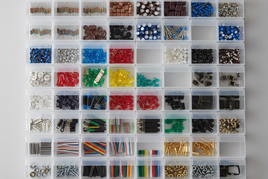
Lifelong Learning Knowledge should be uncompromisingly sought after and freely given away.

20Jul/110

New WiFly Shield Library (fork)

Update: This board design and firmware were just far too buggy. I was very excited to see the Arduino team had answered everyone's request with a WiFi shield and it rocks. http://arduino.cc/en/Main/ArduinoWiFiShield


Just wanted to let folks know that I've forked the alpha 2 library for the WiFly shield to add support for the latest firmware (which happens to fix lots of bugs) but it breaks the library. Sparkfun's WiFly Arduino ShieldI've also added additional functions as well as enabling the NTP server sync for the on board RTC chip. You can find my fork of the library here:

https://github.com/jaycollett/WiFly-Shield


Filed under: Arduino No Comments
5Jul/110

Retro Wifi Radio

I've been working on this project for some time, I had originally read about the concept of hacking the Asus WL-520GU to use as a base for a wifi radio over at MightyOhm.com. In fact, I was so taken by the concept I decided I wanted to build my very own. That was nearly eight months ago....

Jeff over at MightyOhm.com has written a highly detailed step-by-step guide for building a wifi radio just like his and I followed his guide to build mine, with a few major exceptions. First, I wanted to use the Arduino development board. Secondly, I didn't quite like the feel of the user controls with the original design. My goal was to make this really amazing project even easier for folks to build and modify, I figured releasing an Arduino port of his code would accomplish that. If your interested in building one of these radios, I would first suggest you read through his guide and familiarize yourself with the overall concept of how the radio works. Once you have a good understanding of that, you'll be able to better understand my deviations from his project.

The first major change from Jeff's radio is the fact that I used the Arduino development board (with an ATmega328) for my radio and he uses just the bare brains of the Arduino, the ATmega168. While the chips are nearly identical, I've chosen to write all the code in the native Arduino coding language and he's using WinAVR and C to program the chip. The second major change is the fact that Jeff's radio has the LCD display the radio station information on a 20X2 LCD display with data coming from the router. I've opted to use a 20X4 LCD display and have the station information statically coded in the Arduino sketch.

The reason behind the first deviation from his project, is that I felt it would be easier for folks to build off the project if I used the standard Arduino development board. I also wanted to simplify the logistics of all the auxiliary electronics in the radio by utilizing a custom-built shield for the Arduino. The rational behind my second deviation to have the radio stations statically coded in the Arduino sketch was driven by the fact that I felt like the user interface was too slow to update the LCD with information for the user. It felt sluggish to me and tedious. I wanted something snappier and with a bit more tactile feel to it. Switching his 10k potentiometer to a 12 position rotary switch and utilizing some nifty voltage dividers on the shield, I was able to accomplish what I wanted.

The Code

The code has been through quite a few revisions, it taught me alot about the importance of minimizing your use of SRAM in a micro-controller, the Arduino (ATmega328) only has 2k so it's a precious commodity and I didn't appreciate that in the first few revisions of the code. It left me with a radio that would randomly crash, once I developed an appreciation for the use of SRAM and rewrote the code to eliminate my wasteful use of it, I was awarded with a rock solid radio. Be very careful when working with strings especially, you'll use up the RAM and it'll cause your code to behave in some really weird ways. I found a few great blogs about the subject which I think anyone who is serious about the Arduino should read and FULLY understand.

Read this thread and this and finally I'd recommend you read this in regard to memory management with the Arduino.

Also you should be aware that I've changed the two router scripts that Jeff used, I did this to facilitate the Arduino already having the station names and I wanted to offload some of the work to the Arduino from the router. They are included in the zip file I've attached to this post. Just replace his with these if you decide to use my Arduino sketch.


The Radio Box

I purchased my radio box on eBay for approximately $30 US. It was a destroyed 1940's era portable radio which looked much smaller in the pictures, thus the "Retro" in the "Retro Wifi Radio". As you can see from my pictures of the completed radio, it's actually quite large. I'd suggest you find something a bit smaller, although the roominess is nice since I didn't have to worry about squeezing in the speakers and electronics. My primary search criteria for the radio enclosure was one that would allow me to fit the 20x4 LCD in without modifying the box, I'm handy with electronics and mechanical things, not so much with the wood working! Thankfully my father is and he was able to refinish this radio, it looks brand new now and I couldn't have done this project without him, he is after all the man who taught me the basics of mechanics and electronics.


The Shield

I decided very early on that I wanted to build a custom shield for this project. I've since built numerous shields for the Arduino and some day I'll go back and tweak this one with what I've learned. For now, however, this shield works perfectly. The primary purpose of the shield was to allow me to easily connect the LCD and rotary wires to the Arduino, it also helped to keep things a bit more organized. First, the rotary switch; I decided I wanted tactile feedback when switching stations, the rotary switch was my first pick and the 12 position switch was the largest number of positions I could find so that determined the number of radio stations I could have. It also meant that I'd need a few voltage dividers so I could tell which position the switch was at. Tying up 12 pins on the Arduino was out of the question since I had to use 8 pins for the LCD. The voltage divider concept allowed me to only tie up four of the analog pins. Basically each of the four analog pins has three voltage dividers which are easily differentiated using the ADC values. You can refer to the code to see that I look through the four pins to see if they are within one of the three voltage ranges, based on this, I know exactly which position the rotary switch is at.

The shield also has the LCD contrast trim pot, the router serial connection, 5V power in and I brought out a few other pins for future use in addition to a reset button. Like I said, I'd do things a bit differently with this shield given the knowledge I have today but the shield works without issue.


The LCD Display

The LCD display is nice, having the four rows of display makes the information easier to read, I think. I also opted to truncate the data if it's too large to fit on the LCD rather than having it scroll. I personally never liked scrolling text but perhaps someone will take this project and add that feature. I've broken the four rows into:

  1. Station Name
  2. Artist
  3. Song Name
  4. Pre-set radio station number (from 1 to 12 of 12 possible stations)

The idea is that with the Arduino already knows the radio station based on the preset station number so the user gets to see the station names immediately upon changing the rotary switch. Once they leave the switch on a station for a second, the Arduino will display the "Refreshing info" text on the LCD until it can acquire the information from the router. I felt like this makes the interface super intuitive and overall I'm very satisfied with the results.


The Speaker and Audio Amp

For the speaker and audio amp, I decided to hack up some existing speakers I had laying around. The speakers had a volume/on-off switch control had a built-in audio amp and required 12V DC power. This was perfect since the power supply they used was rated for 3.5 amps and I wouldn't have to worry about building an audio amp. I tore out the audio amp board and desoldered the volume control, I used this as the left control knob on my radio to turn the whole system on and off in addition to adjusting the volume. Since I was having a shield manufactured, I decided I'd build a power break-out board with switch control, this way I could have 12V DC coming in to power the speakers and then I could use separate voltage regulators to get the other voltages I needed. Overall, I'm quite happy with the quality of the sound from this setup.


Powering the beast

The speakers that I chose came with a nice power supply that had a current rating that exceeded my calculated requirements by more than 30% which is a design rule I try to use as a minimum. I knew I needed 5V DC for the Arduino and looking at the router's power supply it required 5V DC as well. I measured the current requirements of both the Arduino and the router with my multimeter and decided to use some 5V 1.5A power supply boards I had built for an earlier project. Since I was already using a linear power supply I really could have just used a couple of 5V 1.5A voltage regulators with a heat sink. As I found out after the whole radio was built and used for a few hours, however, some active cooling is necessary for those heat sinks. I had some 5V 40mm fans on hand so I just installed one of those after the fact. You may be wondering why I didn't just use a single regulator setup for both the Arduino and the router? Well, I knew the router would hit ~800mA when streaming and I knew that the Arduino's requirement for ~500mA would push a single 1.5A regulator too hard, besides I have tons of them already and since I had to boards, I used them. If I ever build another one, I'll build a single board with all the regulators and hookups for the different components, I think it'd be cleaner looking and easier to cool with passive cooling.


The Radio in Action

Here is the radio booting up (the router does take that long to boot and start talking to the Arduino) and listening to a few radio stations....

Future Enhancements

Now that I have my working radio I've had time to dream up some enhancements that I think would make it even neater.

1. I want a web interface to change the radio stations that are preset. Would be able to set the station name and enter the URL for the audio stream.

2. Update the shield to put the incoming power on the VIN pin and not the 5V pin.

3. Design build a single board for all the regulators, power requirements of the components. Eliminate the need for active cooling.

4. Perhaps add the option for scrolling text on long artist/song titles.

5. Add an AM/FM tuner chip to shield to allow internet streaming or local radio.

6. Change left knob from a rotary switch to a rotary encoder.


As always, I've included all the schematics, hi-res photos and the Arduino sketch in the attached zip file.


Update (2/11/2013)

I completed a new controller board which includes all the enhancements above and built a PDU (Power Distribution Unit) board as well. I've uploaded all the design files which you can download below. Download "UpdatedWIFIRadio" below.

RetroWifiRadio
Title: RetroWifiRadio (2414 clicks)
Caption:
Filename: retrowifiradio.zip
Size: 6 MB
UpdatedWIFIRadio
Title: UpdatedWIFIRadio (1045 clicks)
Caption:
Filename: updatedwifiradio.zip
Size: 126 KB

24May/110

Oh yeah, I’m licensed!

ARESSo as I talked about in my previous post, I headed up to Dayton Ohio last weekend to witness Hamvention 2011 first hand. Well, what I failed to enlighten the world on is I had been studying to get my license so I could be honest-to-legal HAM operator!

I was able to take the test for free (it's normally ~$30) at Hamvention and once I passed (you doubted me?) had my call letters that night, yep, that's some effecient government work there, isn't it? I picked up a little Wouxun (pronounced woah-sean) radio to get me on the air quickly. With any luck I'll be getting a package in the mail with my base rig, a FT-7900R so I can crank up the amps and actually talk to some folks simplex...


24May/110

A new way to control water!

h20 Shield

Update: I've updated the design of the board and the transistors used to ensure better compatability with the Orbit valves. I was getting reports from folks that some valves would open but not close with the shield. The updated design can be downloaded at the bottom of this post.

I've been working on a rather large project for some time now and while my new h20 shield is just one piece of the larger project, I thought it deserved it's own post and documentation. I can see this shield being quite useful for lots of folks wishing to control water using one of the fairly inexpensive Orbit 62035 garden hose valves.

First, allow me to give credit where credit is due, the hard work for the control circuit and voltage booster came from this incredibly smart gentlemen and the shield wouldn't be possible without his hard work figuring out how to control the valves! His design for controlling the valves works wonderfully!

This shield is a three valve controller with LED indicators for valve status. I used the long headers thinking I'd make the shield stack-able but the 50v cap scrapped that idea. If I make another version, I'll use a different cap/layout to ensure you can stack this shield, as it now, this will just be the top shield in my project. I also used only through-hole parts (I normally would have used nearly all SMT components) to make the shield easier for folks to solder and I had many of the components in through-hole package on hand.

h20 Shield

The circuit is quite simple really, it's comprised of two main parts, the 24V voltage boost circuit which is required to open and close the Orbit water valves and three open/close control circuits. The shield uses 7 digital pins and 3 analog pins. I have one pin each for open and close for each of the three valves, they each drive a transistor which close the 24V through one of the two valve connections. One will open the valve and the other will close it. The final digital pin is used to control the LT1303, when held high, the circuit will shut down thus saving power as the 24V is only needed when opening and closing a valve. I've used the three analog pins to control the LED indicators for the three valves, I needed the other digital pins for other shields that are part of the bigger project I mentioned earlier.

I got the 3.5 mm connectors from SparkFun.com and the rest of the components I either had on-hand or purchased through digikey.com.

I've included high-resolution pictures of the completed board along with the Eagle schematic and board files and a sample Arduino sketch for those interested! As you can see from the video below, the board works perfectly! If you find a use for this design, let me know, I'm always fascinated by how folks use controllers like this!


h2o shield Project Files
Title: h2o shield Project Files (1553 clicks)
Caption:
Filename: h20shield.zip
Size: 13 MB

h2o shield Project Files
Title: h2o shield Project Files (1553 clicks)
Caption:
Filename: h20shield.zip
Size: 13 MB

17May/110

Heading to Dayton Hamvention 2011

Hello fellow geeks, as many of you may already know, Hamvention 2011 is this weekend and I'm heading up to Dayton to check it out. This will be my first time and while I don't have my license just yet (exam is June 21st), I'm stoked to have the opportunity to attend the world's largest HAM convention! I'm also quite lucky to be attending with some great folks who are HAMexperts. Perhaps a Yeasu FT-60 is in my future this weekend? What do you guys reccomend for a first radio?


Filed under: HAM Radio No Comments
16Feb/110

Photography and Electronics, a happy marriage.

Nikon D7000

So with the new baby coming, my wife and I decided we needed to get a new camera. I think it's almost a fad with parents-to-be and while I initially refused the idea of spending money on a new camera (we had a perfectly good point-and-shoot), I eventually caved and started looking. Unfortunately I had forgotten exactly how much I loved photography and quickly realized I wanted a NICE camera. I ended up purchasing the Nikon D7000 and added a few bells and whistles.

Back in the day, I had my own setup to develop B&W photos and digital cameras were just getting affordable enough that I looked into them. It didn't take me long to turn my nose up at them, however. The cameras at the time left a lot to be desired at the price range I could afford so I naively dismissed them and never looked back.

It really wasn't until a few weeks ago that I gave the new DSLR cameras another look and boy am I glad I did! It's amazing how much can change in the span of 10 years! I couldn't believe my eyes, they had finally convinced me that DSLR cameras are as good (if not fabulously better) than my old 35mm film equipment. But I digress...

Having a few days to learn the camera, I quickly realized how symbiotic photography and my electronics really could be! It didn't take me very long to whip up a new circuit to emulate the IR remote that Nikon sales and setup some nice time lapse photography with my Arduino telling my camera to snap a photo every 60 seconds! I was giddy with excitement and after 1/2 hour with my best friend Google, I realized this could go way further. The type of pictures that I could capture with my knowledge of electronics and photography seemed limitless. The articles I had read showed some serious setups which used an Arduino as an intelligent camera trigger for sub-second action shots!

Oh yes, I think I'm going to enjoy (taking pictures of the new baby) this new camera!