Lifelong Learning Knowledge should be uncompromisingly sought after and freely given away.

6Mar/180

Cheap Environment Sensing With ESP8266 & MQTT

Several years back, I got into the home automation game, sadly for me, at the time I was trying to automate "all the things", it was just too chaotic lacking any standardization, was severely limited in what you could do, and was crazy expensive. While trying to find a solution for the IOT cloud issues I was having with my last project, I stumbled upon Home Assistant, specifically HASS.IO. It's an open-source community driven solution for home automation, fully-embraced MQTT (which was what I needed), and was very actively being developed. It solved the need for the project I was finishing as it could ingest MQTT data, store it for a few weeks, and provide graphs, etc. But as I got running with it, I realized how powerful it was and how much more mature and accessible home automation had gotten. Fast-forward a few months, and I've completed my first take at a super inexpensive environment monitor for home automation (or any other need).

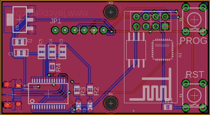
These sensors are super accurate, small, versatile, and best yet, they are super cheap! I designed this particular incarnation to sense the environmental elements, specifically the temperature, the humidity, and the barometric pressure. They are driven by the fantastically cheap ESP8266 and leverage MQTT as the mechanism to feed my HASS.IO instance with the data. For more flexibility and convenience, the boards are designed to support programming of the ESP8266 in-circuit which does drive up the costs but those components are only required if you wish to use this PCB for programming the ESP8266. I'll build the sensors I deploy without them which makes the total cost for a sensor (without the programming bits) $13.91 USD (with USB cable and wall-wart it's $16.14 USD). This makes this sensor far cheaper (and more rewarding) than anything else available on the market.


Sensor Data Populating My HA Instance


I've moved all schematics, code, and images of all my builds to my github.com account. You can find all the files related to this particular build here.

16Feb/140

Closed Loop Monitoring For Motorola Paging System

IMG_20140216_155802824

Finished monitors looking sharp in their enclosures.

In my last post I talked about an issue my company had. We couldn't monitor our paging infrastructure from end-to-end and we couldn't find anybody selling anything that could. Before folks start yapping about pagers, you will see them in the healthcare sector for many more years to come when it comes to contacting a doctor for a life safety issue (cardiac arrest, etc) there is nothing currently sold that is as reliable and timely in the crowded RF world of a hospital.

I had built a prototype monitoring system using one of our pagers and an Arduino paired with a Windows Service. Well, it works and it works wonderfully so I was asked to build three more. Using multiple devices ensures we don't get false positives regarding a system outage due to the device or computer failing.

I've long been a fan of Adafruit and they were my first choice when I had my company order the parts needed to build out the rest of the monitoring devices. I leveraged the Arduino enclosure and the protoshield they sell and everything worked out wonderfully. I must say for a home-built gadget, they look pretty darn good and they perform wonderfully.


My apologizes for the quality of the pictures, had to use the cell....

IMG_20140216_154558527_HDR

This is the back side of the Motorola pager (after the being removed from the case). The two larger wires on the battery leads and the smaller is the signal wire from the positive side of the beeper on the pager.

IMG_20140216_154615645

This is the protoshield from AdaFruit. Getting ready to finish wiring up the battery leads to my 1.5v regulator on the protoshield and the signal wire to the analog pin. The pager is now powered from the 1.5v regulator.

IMG_20140216_155103542_HDR

Finished the wiring. All three wires! This is a much simpler setup than the original prototype.


13Feb/130

Healthy Habitats For Home Labs

iStock_000015238547XSmallI've slowly been able to expand my home lab to include the type of equipment that allows me to continually improve my technical skills as well as experiment with home automation and DIY electronics. As my home lab has grown so has the need to ensure it's kept healthy. One way to ensure it stays healthy is to make sure it's got a nice  comfortable habitat in which to work and live.

My first feeble attempt to monitor the environment where I keep my server rack was to buy a cheap-o temp and humidity meter from eBay.  It worked in so much as I could tell what the temperature and humidity was if I bothered to go down to the basement and look. I'm lazy, heck I have IP KVMs so I don't have to go downstairs to reboot a server, I'm not going to go down there to check the environmental conditions. Something better had to be implemented....

I started looking for environmental monitors/sensors on eBay thinking I could pick something up cheap from one of the numerous companies that sell used computer equipment. Data centers are always upgrading such things and I was confident I'd get something to meet my needs for less than $100USD. Wow, I was ever so wrong. I found some things around the $100USD range but they typically required other pieces or sensors that costs as much or more. This was starting to suck.

Not sure why it took so long, but I finally remembered I had purchased a temperature and humidity sensor from AdaFruit.com many months back for a project I hadn't completed. I also remembered I had an Ethernet shield and I always have a few Arduinos on hand. I had struck gold, I'll build my on networked environmental sensor and I can do it for FREE (as I already owned all the pieces).

Thanks to AdaFruit.com's learning site, I was able to get my DHT22 temperature and humidity sensor working in just a few minutes but I needed some way to get to the data remotely over the network. I hooked up my Ethernet shield and started messing about with building a HTTP client and after a bit realized there had to be someone who had done this already. I found this article which leveraged the Ethernet shield to log the data to a cloud service which had a nice user interface for making sense of the data points I was capturing. Exosite was going to be a great, no fantastic solution! I downloaded the Arduino library for Exosite and I was done in about 30 minutes.

20130213-164324.jpgThis is why I love Arduinos and the community of Arduino users. I was able to build an environmental sensor that was networked, captured historical data points and even has alerting features (via email) in about an hour and for about $75USD in parts.

Check out my Exosite portal here.

Now I've just got find a nice way to mount this in my rack and add a display for local viewing of the temperature and humidity for those times I actually am standing in front of the rack. But I'll save that for another post....

My example code and high resolution pictures can be downloaded below.

LabSensor
Title: LabSensor (1978 clicks)
Caption:
Filename: labsensor.zip
Size: 2 MB

25Jul/120

Why did I wait so long to toast my boards?

PCB Toaster OvenI've recently redesigned my Retro WiFi Radio project to include some "extra" functionality and the design requirements required some tiny spacing of the components in addition to some tiny SMD parts. While I'm all for hand soldering SMD when needed, I wasn't looking forward to attempting this board build by hand...I really needed to look for a better, faster and more reliable way to solder SMD boards. I'd read articles from Adafruit and some other sites about utilizing electric skillets to re-flow boards but I've also read plenty that say it's not the ideal way to re-flow. I even went  as far as to "Watch" some eBay listings for a few cheap Chinese re-flow ovens. I knew folks had been having lots of luck using a PID controller and a toaster oven and after reading reviews about those cheap Chinese re-flow ovens, I figured my $50 investment in a toaster oven from wally world would be the safest gamble. I knew I wanted a toaster with no digital controls (easier to hack up, I suspected) and dual top and bottom heating elements. I also had read some good reports using toaster ovens with a fan which supposedly prevented hot/cold spots in the oven. I found a Black and Decker at Wal-Mart for about $40 that fit the bill perfectly so I made the plunge, I sure hope it would reach high enough temps fast enough to hold a good re-flow profile.... The first test for the toaster before tearing it apart was to ensure it'd get hot enough without any modifications.

My particular oven has both a "Baking" and "Toasting" settings with the difference being the "Baking" setting enables the convection fan. I tested the oven in both settings to ensure it'd easily exceed the required 250C my lead-free profile would require for re-flow. It didn't take any time at all for the toaster to exceed my temperature requirements in both settings. Looks like I got myself a champ here folks! Given the fact that I had already purchased an appropriate solid state relay for a different project and I had a spare Arduino laying around, I knew I could quickly throw together a PID controller and test the toaster's ability to hold a profile. I used a sketch from these great folks (which they use for their Arduino re-flow shield) and an LCD display I had laying about. I had a working PID controller in about 45 minutes. So far, this project was looking like it was going to be super easy! Why hadn't I done this before? Using my Fluke meter (with temp probe), I manually charted the temperatures of 3 re-flow runs and while not as accurate as an industrial re-flow oven, I think it'll do just fine. My first few boards worked perfectly and I must say, it's WAY faster and easier than soldering by hand! Bring on those 0603 resistors now!  

Update:

Not one to leave good enough alone, I decided there were a few easy things I could do to improve the responsiveness of the toaster and help it follow my profile more accurately. Here's what I did to the toaster to "improve" it and the results. 1. Added reflective "flue tape" to the inside of the toaster's internal metal walls (back wall and bottom with ceramic fill inside cavity) as well as the glass front door (minus the "peep" window). 2. Filled internal voids with ceramic fiber insulation wool. Got some cheap from eBay

Unaltered Toaster:

Time to 250C (Toast Setting): 3:41.3 Time to 250C (Bake Setting): 6:46.9

"Improved" Toaster:

Time to 250C (Toast Setting): 2:25.8 Time to 250C (Bake Setting): 3:53.6

20Jul/110

New WiFly Shield Library (fork)

Update: This board design and firmware were just far too buggy. I was very excited to see the Arduino team had answered everyone's request with a WiFi shield and it rocks. http://arduino.cc/en/Main/ArduinoWiFiShield


Just wanted to let folks know that I've forked the alpha 2 library for the WiFly shield to add support for the latest firmware (which happens to fix lots of bugs) but it breaks the library. Sparkfun's WiFly Arduino ShieldI've also added additional functions as well as enabling the NTP server sync for the on board RTC chip. You can find my fork of the library here:

https://github.com/jaycollett/WiFly-Shield


Filed under: Arduino No Comments
5Jul/110

Retro Wifi Radio

I've been working on this project for some time, I had originally read about the concept of hacking the Asus WL-520GU to use as a base for a wifi radio over at MightyOhm.com. In fact, I was so taken by the concept I decided I wanted to build my very own. That was nearly eight months ago....

Jeff over at MightyOhm.com has written a highly detailed step-by-step guide for building a wifi radio just like his and I followed his guide to build mine, with a few major exceptions. First, I wanted to use the Arduino development board. Secondly, I didn't quite like the feel of the user controls with the original design. My goal was to make this really amazing project even easier for folks to build and modify, I figured releasing an Arduino port of his code would accomplish that. If your interested in building one of these radios, I would first suggest you read through his guide and familiarize yourself with the overall concept of how the radio works. Once you have a good understanding of that, you'll be able to better understand my deviations from his project.

The first major change from Jeff's radio is the fact that I used the Arduino development board (with an ATmega328) for my radio and he uses just the bare brains of the Arduino, the ATmega168. While the chips are nearly identical, I've chosen to write all the code in the native Arduino coding language and he's using WinAVR and C to program the chip. The second major change is the fact that Jeff's radio has the LCD display the radio station information on a 20X2 LCD display with data coming from the router. I've opted to use a 20X4 LCD display and have the station information statically coded in the Arduino sketch.

The reason behind the first deviation from his project, is that I felt it would be easier for folks to build off the project if I used the standard Arduino development board. I also wanted to simplify the logistics of all the auxiliary electronics in the radio by utilizing a custom-built shield for the Arduino. The rational behind my second deviation to have the radio stations statically coded in the Arduino sketch was driven by the fact that I felt like the user interface was too slow to update the LCD with information for the user. It felt sluggish to me and tedious. I wanted something snappier and with a bit more tactile feel to it. Switching his 10k potentiometer to a 12 position rotary switch and utilizing some nifty voltage dividers on the shield, I was able to accomplish what I wanted.

The Code

The code has been through quite a few revisions, it taught me alot about the importance of minimizing your use of SRAM in a micro-controller, the Arduino (ATmega328) only has 2k so it's a precious commodity and I didn't appreciate that in the first few revisions of the code. It left me with a radio that would randomly crash, once I developed an appreciation for the use of SRAM and rewrote the code to eliminate my wasteful use of it, I was awarded with a rock solid radio. Be very careful when working with strings especially, you'll use up the RAM and it'll cause your code to behave in some really weird ways. I found a few great blogs about the subject which I think anyone who is serious about the Arduino should read and FULLY understand.

Read this thread and this and finally I'd recommend you read this in regard to memory management with the Arduino.

Also you should be aware that I've changed the two router scripts that Jeff used, I did this to facilitate the Arduino already having the station names and I wanted to offload some of the work to the Arduino from the router. They are included in the zip file I've attached to this post. Just replace his with these if you decide to use my Arduino sketch.


The Radio Box

I purchased my radio box on eBay for approximately $30 US. It was a destroyed 1940's era portable radio which looked much smaller in the pictures, thus the "Retro" in the "Retro Wifi Radio". As you can see from my pictures of the completed radio, it's actually quite large. I'd suggest you find something a bit smaller, although the roominess is nice since I didn't have to worry about squeezing in the speakers and electronics. My primary search criteria for the radio enclosure was one that would allow me to fit the 20x4 LCD in without modifying the box, I'm handy with electronics and mechanical things, not so much with the wood working! Thankfully my father is and he was able to refinish this radio, it looks brand new now and I couldn't have done this project without him, he is after all the man who taught me the basics of mechanics and electronics.


The Shield

I decided very early on that I wanted to build a custom shield for this project. I've since built numerous shields for the Arduino and some day I'll go back and tweak this one with what I've learned. For now, however, this shield works perfectly. The primary purpose of the shield was to allow me to easily connect the LCD and rotary wires to the Arduino, it also helped to keep things a bit more organized. First, the rotary switch; I decided I wanted tactile feedback when switching stations, the rotary switch was my first pick and the 12 position switch was the largest number of positions I could find so that determined the number of radio stations I could have. It also meant that I'd need a few voltage dividers so I could tell which position the switch was at. Tying up 12 pins on the Arduino was out of the question since I had to use 8 pins for the LCD. The voltage divider concept allowed me to only tie up four of the analog pins. Basically each of the four analog pins has three voltage dividers which are easily differentiated using the ADC values. You can refer to the code to see that I look through the four pins to see if they are within one of the three voltage ranges, based on this, I know exactly which position the rotary switch is at.

The shield also has the LCD contrast trim pot, the router serial connection, 5V power in and I brought out a few other pins for future use in addition to a reset button. Like I said, I'd do things a bit differently with this shield given the knowledge I have today but the shield works without issue.


The LCD Display

The LCD display is nice, having the four rows of display makes the information easier to read, I think. I also opted to truncate the data if it's too large to fit on the LCD rather than having it scroll. I personally never liked scrolling text but perhaps someone will take this project and add that feature. I've broken the four rows into:

  1. Station Name
  2. Artist
  3. Song Name
  4. Pre-set radio station number (from 1 to 12 of 12 possible stations)

The idea is that with the Arduino already knows the radio station based on the preset station number so the user gets to see the station names immediately upon changing the rotary switch. Once they leave the switch on a station for a second, the Arduino will display the "Refreshing info" text on the LCD until it can acquire the information from the router. I felt like this makes the interface super intuitive and overall I'm very satisfied with the results.


The Speaker and Audio Amp

For the speaker and audio amp, I decided to hack up some existing speakers I had laying around. The speakers had a volume/on-off switch control had a built-in audio amp and required 12V DC power. This was perfect since the power supply they used was rated for 3.5 amps and I wouldn't have to worry about building an audio amp. I tore out the audio amp board and desoldered the volume control, I used this as the left control knob on my radio to turn the whole system on and off in addition to adjusting the volume. Since I was having a shield manufactured, I decided I'd build a power break-out board with switch control, this way I could have 12V DC coming in to power the speakers and then I could use separate voltage regulators to get the other voltages I needed. Overall, I'm quite happy with the quality of the sound from this setup.


Powering the beast

The speakers that I chose came with a nice power supply that had a current rating that exceeded my calculated requirements by more than 30% which is a design rule I try to use as a minimum. I knew I needed 5V DC for the Arduino and looking at the router's power supply it required 5V DC as well. I measured the current requirements of both the Arduino and the router with my multimeter and decided to use some 5V 1.5A power supply boards I had built for an earlier project. Since I was already using a linear power supply I really could have just used a couple of 5V 1.5A voltage regulators with a heat sink. As I found out after the whole radio was built and used for a few hours, however, some active cooling is necessary for those heat sinks. I had some 5V 40mm fans on hand so I just installed one of those after the fact. You may be wondering why I didn't just use a single regulator setup for both the Arduino and the router? Well, I knew the router would hit ~800mA when streaming and I knew that the Arduino's requirement for ~500mA would push a single 1.5A regulator too hard, besides I have tons of them already and since I had to boards, I used them. If I ever build another one, I'll build a single board with all the regulators and hookups for the different components, I think it'd be cleaner looking and easier to cool with passive cooling.


The Radio in Action

Here is the radio booting up (the router does take that long to boot and start talking to the Arduino) and listening to a few radio stations....

Future Enhancements

Now that I have my working radio I've had time to dream up some enhancements that I think would make it even neater.

1. I want a web interface to change the radio stations that are preset. Would be able to set the station name and enter the URL for the audio stream.

2. Update the shield to put the incoming power on the VIN pin and not the 5V pin.

3. Design build a single board for all the regulators, power requirements of the components. Eliminate the need for active cooling.

4. Perhaps add the option for scrolling text on long artist/song titles.

5. Add an AM/FM tuner chip to shield to allow internet streaming or local radio.

6. Change left knob from a rotary switch to a rotary encoder.


As always, I've included all the schematics, hi-res photos and the Arduino sketch in the attached zip file.


Update (2/11/2013)

I completed a new controller board which includes all the enhancements above and built a PDU (Power Distribution Unit) board as well. I've uploaded all the design files which you can download below. Download "UpdatedWIFIRadio" below.

RetroWifiRadio
Title: RetroWifiRadio (2412 clicks)
Caption:
Filename: retrowifiradio.zip
Size: 6 MB
UpdatedWIFIRadio
Title: UpdatedWIFIRadio (1043 clicks)
Caption:
Filename: updatedwifiradio.zip
Size: 126 KB