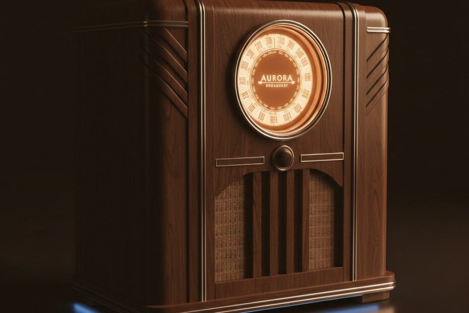
Lifelong Learning Knowledge should be uncompromisingly sought after and freely given away.

24May/110

A new way to control water!

h20 Shield

Update: I've updated the design of the board and the transistors used to ensure better compatability with the Orbit valves. I was getting reports from folks that some valves would open but not close with the shield. The updated design can be downloaded at the bottom of this post.

I've been working on a rather large project for some time now and while my new h20 shield is just one piece of the larger project, I thought it deserved it's own post and documentation. I can see this shield being quite useful for lots of folks wishing to control water using one of the fairly inexpensive Orbit 62035 garden hose valves.

First, allow me to give credit where credit is due, the hard work for the control circuit and voltage booster came from this incredibly smart gentlemen and the shield wouldn't be possible without his hard work figuring out how to control the valves! His design for controlling the valves works wonderfully!

This shield is a three valve controller with LED indicators for valve status. I used the long headers thinking I'd make the shield stack-able but the 50v cap scrapped that idea. If I make another version, I'll use a different cap/layout to ensure you can stack this shield, as it now, this will just be the top shield in my project. I also used only through-hole parts (I normally would have used nearly all SMT components) to make the shield easier for folks to solder and I had many of the components in through-hole package on hand.

h20 Shield

The circuit is quite simple really, it's comprised of two main parts, the 24V voltage boost circuit which is required to open and close the Orbit water valves and three open/close control circuits. The shield uses 7 digital pins and 3 analog pins. I have one pin each for open and close for each of the three valves, they each drive a transistor which close the 24V through one of the two valve connections. One will open the valve and the other will close it. The final digital pin is used to control the LT1303, when held high, the circuit will shut down thus saving power as the 24V is only needed when opening and closing a valve. I've used the three analog pins to control the LED indicators for the three valves, I needed the other digital pins for other shields that are part of the bigger project I mentioned earlier.

I got the 3.5 mm connectors from SparkFun.com and the rest of the components I either had on-hand or purchased through digikey.com.

I've included high-resolution pictures of the completed board along with the Eagle schematic and board files and a sample Arduino sketch for those interested! As you can see from the video below, the board works perfectly! If you find a use for this design, let me know, I'm always fascinated by how folks use controllers like this!


h2o shield Project Files
Title: h2o shield Project Files (1553 clicks)
Caption:
Filename: h20shield.zip
Size: 13 MB

h2o shield Project Files
Title: h2o shield Project Files (1553 clicks)
Caption:
Filename: h20shield.zip
Size: 13 MB

16Feb/110

Photography and Electronics, a happy marriage.

Nikon D7000

So with the new baby coming, my wife and I decided we needed to get a new camera. I think it's almost a fad with parents-to-be and while I initially refused the idea of spending money on a new camera (we had a perfectly good point-and-shoot), I eventually caved and started looking. Unfortunately I had forgotten exactly how much I loved photography and quickly realized I wanted a NICE camera. I ended up purchasing the Nikon D7000 and added a few bells and whistles.

Back in the day, I had my own setup to develop B&W photos and digital cameras were just getting affordable enough that I looked into them. It didn't take me long to turn my nose up at them, however. The cameras at the time left a lot to be desired at the price range I could afford so I naively dismissed them and never looked back.

It really wasn't until a few weeks ago that I gave the new DSLR cameras another look and boy am I glad I did! It's amazing how much can change in the span of 10 years! I couldn't believe my eyes, they had finally convinced me that DSLR cameras are as good (if not fabulously better) than my old 35mm film equipment. But I digress...

Having a few days to learn the camera, I quickly realized how symbiotic photography and my electronics really could be! It didn't take me very long to whip up a new circuit to emulate the IR remote that Nikon sales and setup some nice time lapse photography with my Arduino telling my camera to snap a photo every 60 seconds! I was giddy with excitement and after 1/2 hour with my best friend Google, I realized this could go way further. The type of pictures that I could capture with my knowledge of electronics and photography seemed limitless. The articles I had read showed some serious setups which used an Arduino as an intelligent camera trigger for sub-second action shots!

Oh yes, I think I'm going to enjoy (taking pictures of the new baby) this new camera!

24Nov/100

Homemade Blinky Christmas Ornaments

Small picture of PCBLast year I decided to jazz up our family Christmas cards with LED power, inspired by this article. While I was totally happy with the cards I sent out, I was wanting something a bit more this year so I've decided to take it one step further and create Christmas ornaments for our family that will be sent with this year's Christmas cards.

I had a few criteria that drove my design for the ornament not to mention I had a very short timeframe so simplicity was important:

1. Have the same shape as a typical Christmas ornament (it is an ornament after all).
2. Lots of LEDs, folks in my family love LED blinky things.
3. Battery powered and last as long as possible on battery.
4. Hackable. I wanted the board to be easily hacked by family and friends that were so inclined.
5. Maximize the visual appearance of the front of the board (no through-hole components), I was also going to put a Christmas message on the front in silkscreen.

After a few hours piecing together the schematic, I was pretty happy with the reChristmasOrnamentsults. Ironically when I went to start the board design I ran into a simple but problematic issue of how to evenly place the LEDs on the round board, being the true geek that I am, I wrote a C# app which you can see in the ZIP file attached to this post. It gave me the x and y coordinates for each LED given the radius, origin and degree. Being late at night when I finally got around to laying out the board, this was a true life saver!

Once I had the LEDs placed, I decided to go back and add some blue and white LEDs on the neck of the board to enhance the "blinky" factor. Skip ahead 4 more hours and I had finished the board layout. I always give myself a day or two after the board is done before I come back to it and QA the layout, saves me tons of time staring at a problem and not seeing it! My QA found several issues and once resolved I sent it off to the boys over at BatchPCB.com for fabrication.

Fabrication typically takes three weeks or more but I was nicely surprised when my boards shipped after only 7 days and being the OCD type I am, I had to assembly one of the boards as soon as they came in the mail. It took me about 3 hours to assemble the first board, I was being overly cautious and deliberate in each solder and relearning how to use my hot air rework station. The total time for the first board included soldering up my homemade ATMega TQFP programming board which I used to burn the Arduino Uno boot loader onto the ATMega chips I had leftover from a previous project. I'll post about it in more detail later, I have a few minor tweaks to make to the design before I think I'll be totally happy with it, but it served me well for this project.

With the boot loader loaded, the final test would be attempting to load a sketch on it using my FTDI cable. To my total elation, it loaded the sketch without issue and my blinky utopia began! I was absolutely filled with joy when those LEDs started blinking away, who knew something so trivial could be so satisfying. I learned a lot with this project and I gained some important confidence in my design and layout skills which should serve me well with my next project.

As for battery life, I've adjusted some of the animations so that I could eliminate having all the LEDs on for extended periods of time and found that I was able to leave the ornament on constantly and the batteries died (the board actually froze) after about 40 hours. I thought about putting in a sleep mode after 6 hours of use or something but I think I'll pass and allow the user to just remember to shut them off, heck those inclined could do it themselves!

Well, I'm giving out the ornaments on Thursday (Thanksgiving) so that friends and family can enjoy them on their trees this holiday season, I sure do hope they enjoy them as much as I enjoyed building and designing them! Check out a video of them in action below!

ChristmasOrnament
Title: ChristmasOrnament (1151 clicks)
Caption:
Filename: christmasornament.zip
Size: 22 MB

ChristmasOrnament
Title: ChristmasOrnament (1151 clicks)
Caption:
Filename: christmasornament.zip
Size: 22 MB

10Nov/100

Arduino Clone Powered RGB Keyboard Light

I recently remodeled my office as I'll be working from home full-time starting in March, it's amazing what you can do with $1k dollars at Ikea! Anyhow, love my office setup, especially my desk but I had one nagging issue, I couldn't see the keys of my keyboard easily when the office was dark. My wife subltly suggested I get some sort of light to put underneath my desk to illuminate the keyboard. Ah, how I love my wife and her fantastic ideas...   

Obviously, I wouldn't settle for some store bought device, I'm a self-declared "Maker" after all! After several days of tossing around ideas in my head, I decided it'd be super neato to have an RGB LED board under my desk and have it connected and powered by my computer. I'd then have some software sit in my system tray so I could control the board (colors and etc). Yeah, that's exactly what I needed!

So, yesterday I decided I'd set out to build it with only the parts I had on hand, I'm having a baby and thusly on a very restricted hobby budget!

Since I'd be etching the board myself, I knew I'd use through hole components to make life easier and I centered the project around an ATMega328 since I wanted to use serial communication with my PC and the quickest path was to use Arduino programming language (using a FTDI cable). I also wanted to utilize some 5mm common annode RGB leds I had on hand from a previous project but I wanted at least 5 to make sure I had good illumination on the keyboard and I wanted to use PWM to allow color mixing...well, a few 2907A transistors and a dozen or more resistors later I had a schematic I could be proud of. 

Eagle Board Layout for my RGB keyboard light

The layout of the board was easy, I had a 3"x4" single sided copper photoetch board, so I laid all my components out to fit the whole board (I didn't want to cut it). I also learned the hard way that small traces are a pain in the butt when etching your own boards so I set my traces to 24mil, genrously large enough to not create issues during the etch. I didn't get any pictures of the board before it was mounted, sorry. You can always refer to the board image in the zip file attached to this post.

Once I had soldered all my components on the board, I threw in an ATMega328 micro that already had the Arduino bootloaded burned. Hooked up my FTDI cable and my test sketch worked flawlessly. Whew, nothing like going from concept to finished board with no testing to get the nerves going!

With the board testing out good, I set about coding up a C# app to control it. I had previously worked with serial comunications using C# and an Arduino which I talked about in this post so the C# code was really more about figuring out how to get a sys-tray app working as I wanted than worrying with the serial communications. I think it took me about 2 hours from start to finish to get things to a point I was happy with (nice and quick not nice and neat). I'm a developer by trade so I knew all along this would be the easiest part for me.

Well, a very quick project for me, one I'm quite proud of actually. As always I've attached high resolution pictures, eagle schematics, Arduino sketch and this time the Visual Studio solution in the zip below.

Drop me a note if you have any questions about this project, I think it's a fun and easy project for folks to test out thier etching and coding skillz!

Check out the videos below to see the software and board in action!

KeyBoardLightProject
Title: KeyBoardLightProject (1184 clicks)
Caption:
Filename: keyboardlightproject.zip
Size: 19 MB

KeyBoardLightProject
Title: KeyBoardLightProject (1184 clicks)
Caption:
Filename: keyboardlightproject.zip
Size: 19 MB

22Nov/090

MAX7219 LED Driver With Arduino

Using MAX7219 with Arduino

 I am working on a larger projected and have decided the Arduino ATMEGA328 (which seem to be hard to find in stock online) would be the best choice for the project. Seeing as how the project is going to utilize 7-Segment multi-digit displays (common cathode), I knew I had to find a LED driver, no other realistic way to drive the displays. Anyhow, I picked up some LED drivers from one of my favorite companies, MAXIM. I chose the MAX7219 as it's well documented and works with the existing LED driver Arduino library. This prototype was to ensure I had everything working as I would have expected. In this prototype, I utilized a fixed Rset value. I'll use a trim pot in my other project (which I'll write up next weekend). If you have any questions on wiring up one of these LED drivers with Arduino, check this site out and this one.

8Oct/090

Finally built my first Arduino

Basic ArduinoI finally got my order in from SparkFun.com this morning and couldn't wait to try my hand at building out my Arduino boards. I've talked about them before here. The challenge was the USB to Serial chip which is a SMD chip. With my new iron and some good quality solder wick, I was able to get them on the first time with little to no effort. The iron is a HUGE leap forward for me. I can't rave enough about how much I love it, granted I'm comparing it to my Radio Shack iron which is lovingly called a "fire starter" by most. Anyhow, built these boards and plugged them in to see if all was good, whatta ya know, right off the bat I was able to upload sketches to them both! I've got a few tweaks I'm going to make to this design tho, I"m going to add SMD leds for USB RX/TX activity and rearrange the boards just a bit. If you are wondering why on earth I'd have a vertical USB plug, it's because I plan on using these boards for another project and that's the orientation I wanted. You can easily switch the part out for the vertical one in Eagle. If you want the schematic or board files, they are attached to my previous post here. As for costs of these, I've got less than ~$15 US in each.