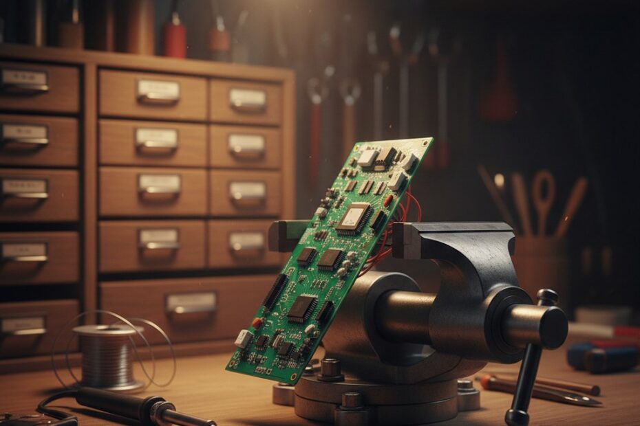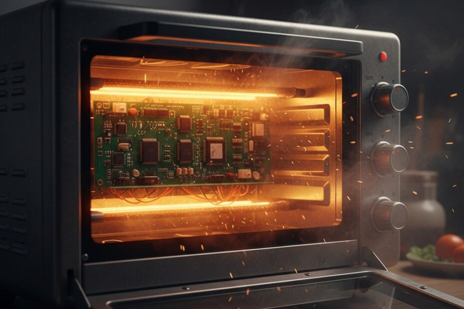
DIY PCB Reflow Soldering with a $40 Toaster Oven
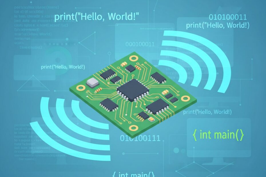
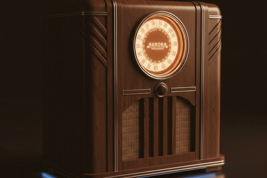
I’ve recently redesigned my Retro WiFi Radio project to include some “extra” functionality and the design requirements required some tiny spacing of the components in addition to some tiny SMD parts. While I’m all for… DIY PCB Reflow Soldering with a $40 Toaster Oven